Code Samples
The long list of ready-to-use source code samples
The following Visual Studio sample projects are located under the product installation folder (Demos and Samples sub-folders). Each code sample is delivered in four versions: Windows Forms and Windows Presentation Foundation platforms, C# and VB.NET programming languages.
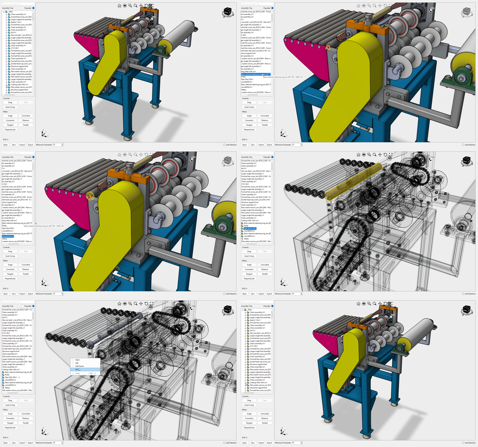
AssemblyDemo
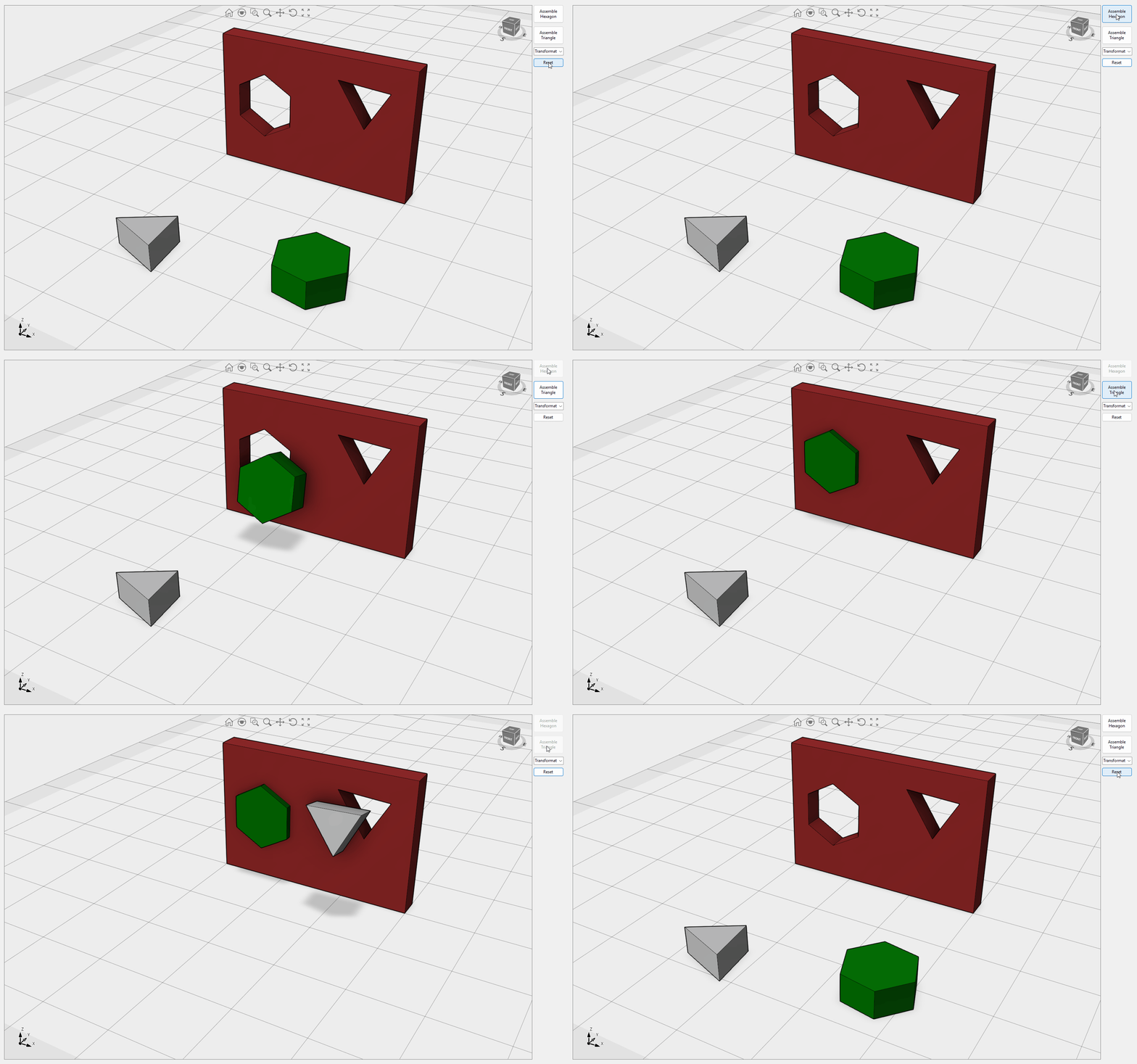
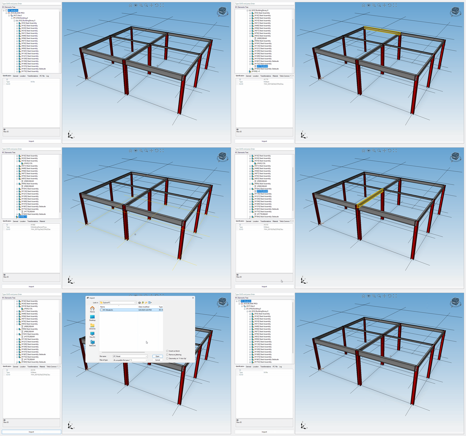
This sample showcases Eyeshot's capability to handle large assemblies. It includes several useful commands such as Form New, Dissolve, Edit Structure, Make Independent, Edit Part, Edit Assembly, Edit Parent, and Moved with Triad. You can control selection, visibility, and selectability at the instance level. AssemblyDemo allows selection in branch or leaf mode and commands to open/save and import/export in IGES/STEP file formats. Asynchronous regeneration, disabled shadows, disabled reflection, disabled silhouette curves, and show center of rotation are the default settings for this sample. Video1, Video2, Video3
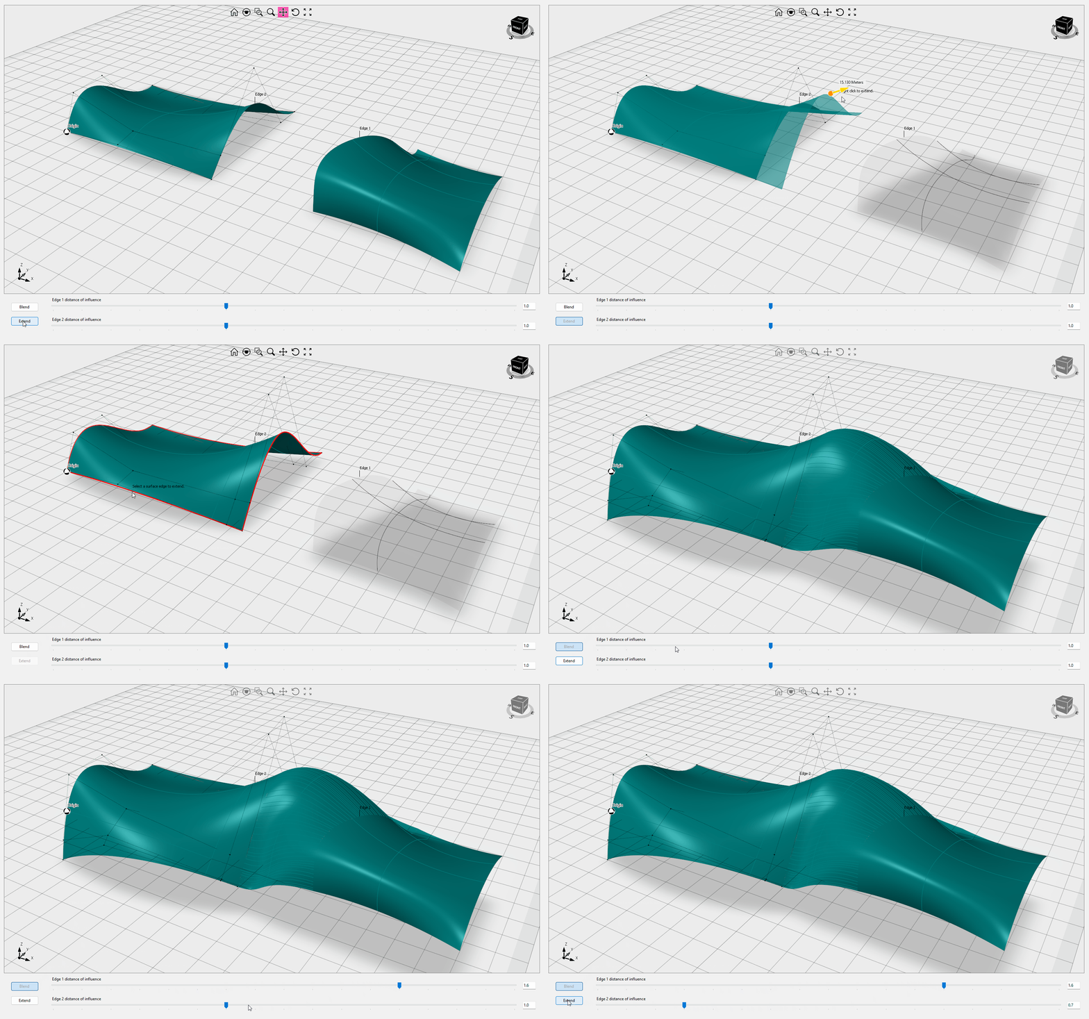
BlendSurface Ultimate Fem
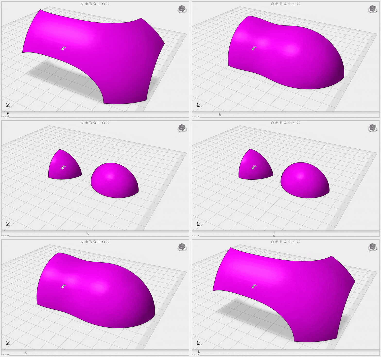
This sample explains how to build a blend surface between two surface edges. You can interactively change the influence of each edge. The Extend button allows you to smoothly extend the surface edges. Video1
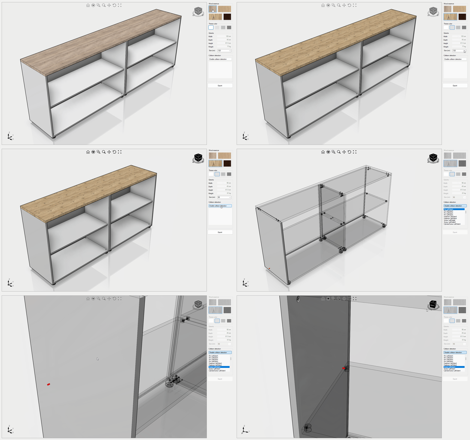
CabinetDesigner Ultimate Fem
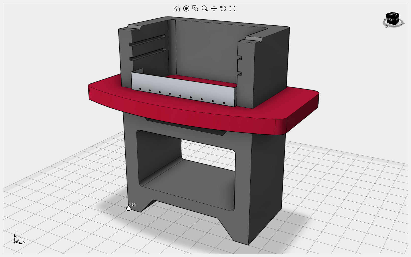
This sample details how to create a cabinet from scratch and verify the assembly using collision detection. Video1
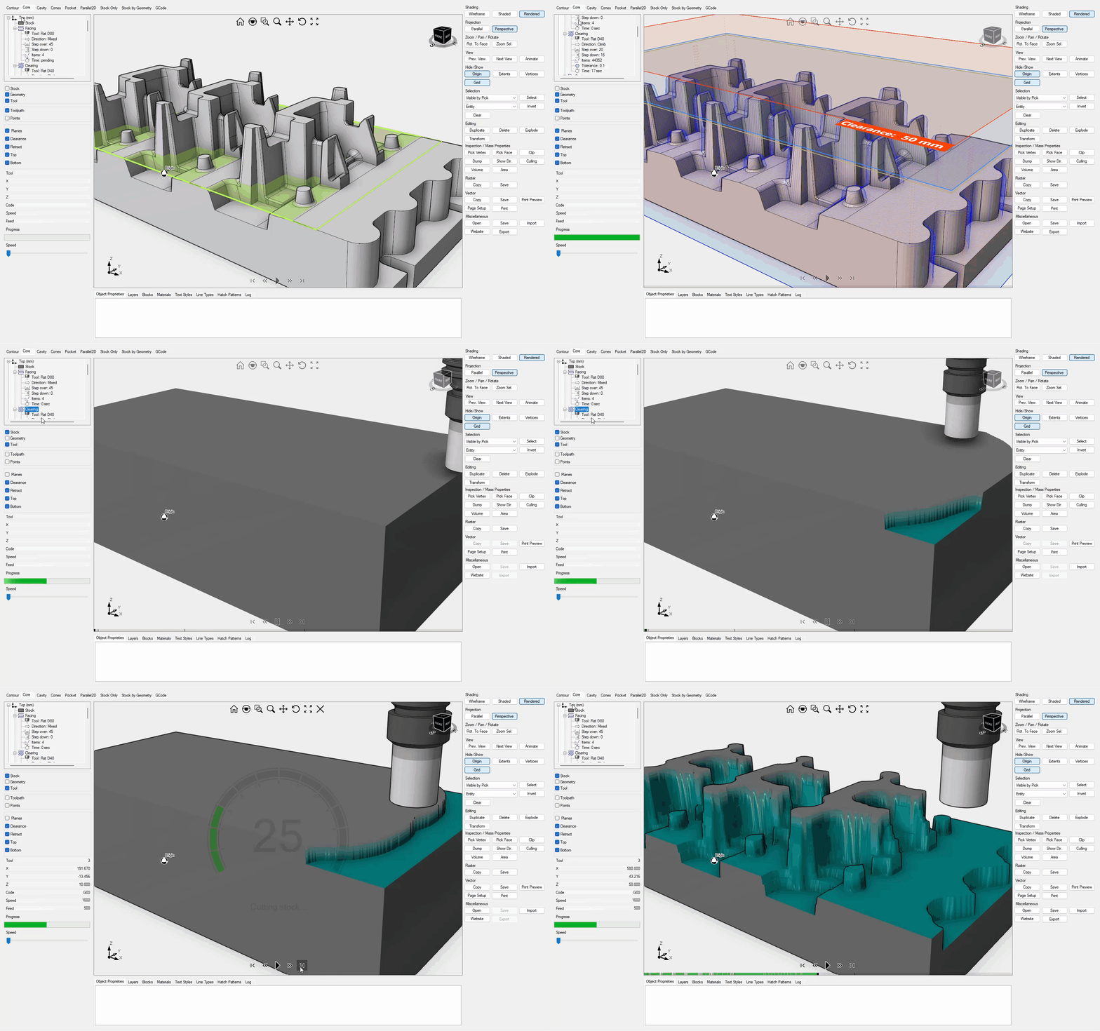
CamDemo
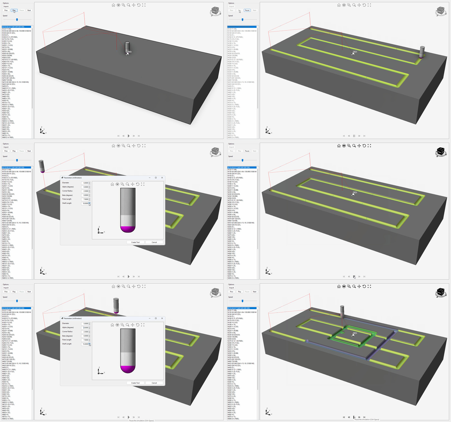
This sample explains how to create 2x and 3x toolpaths and simulate material removal. Video1
CollisionDetection
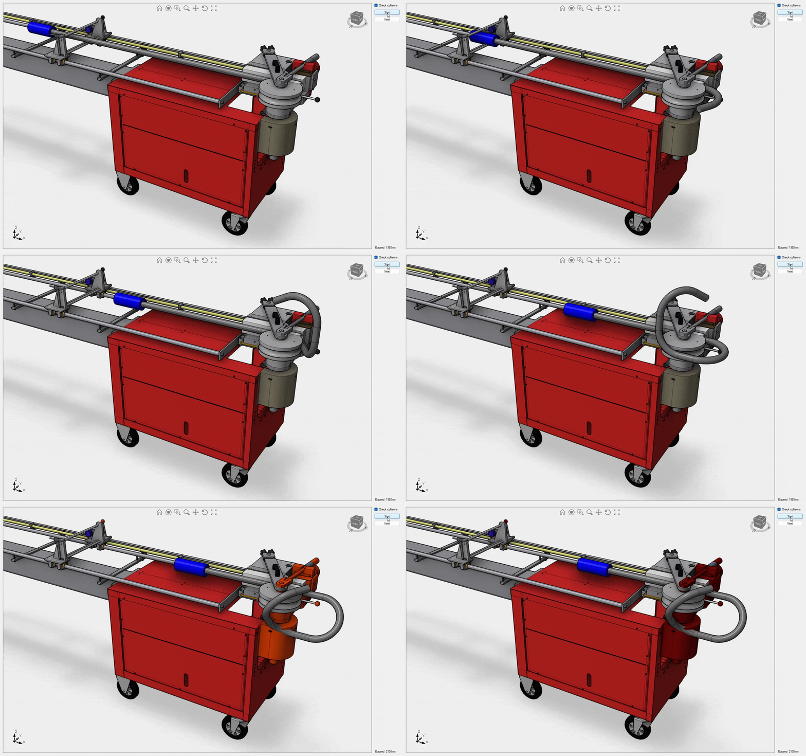
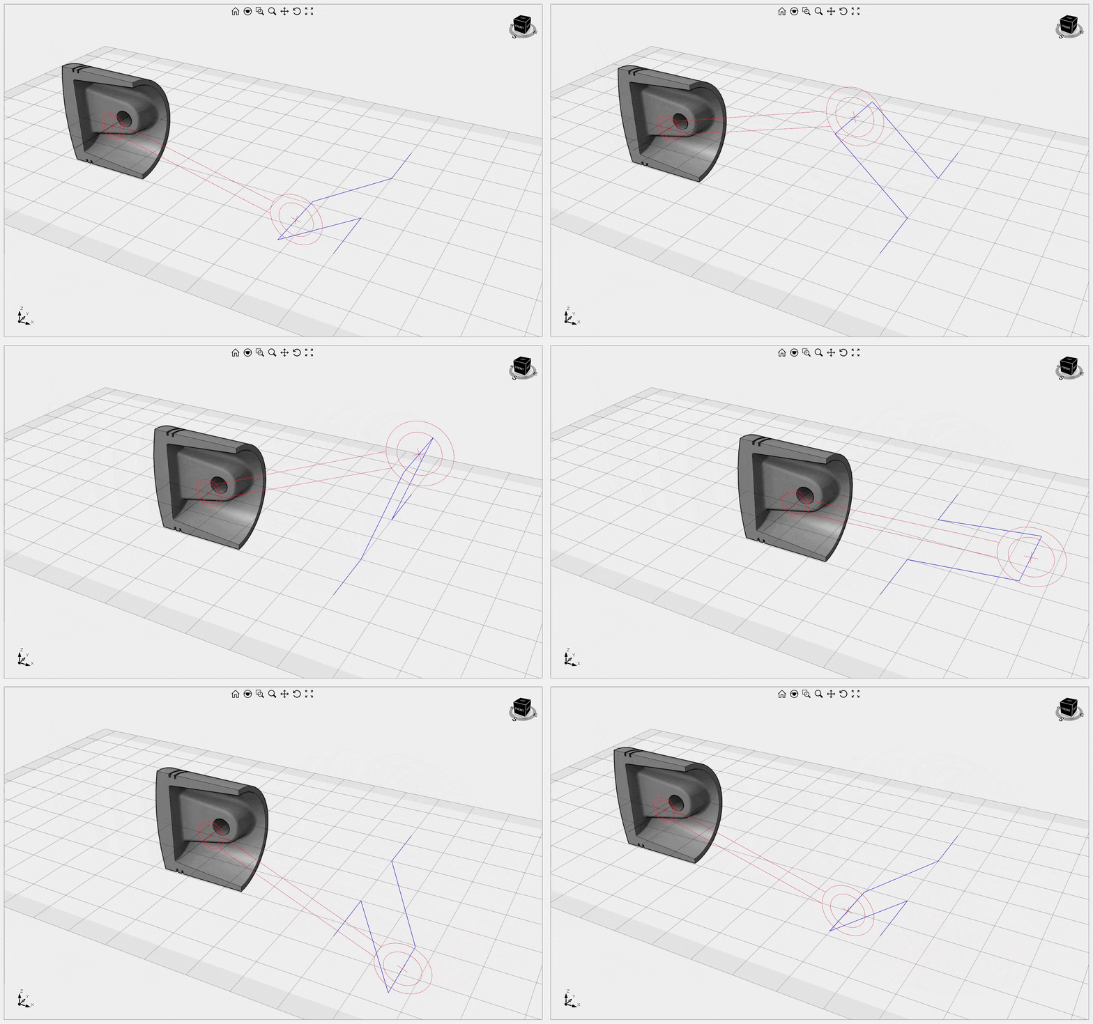
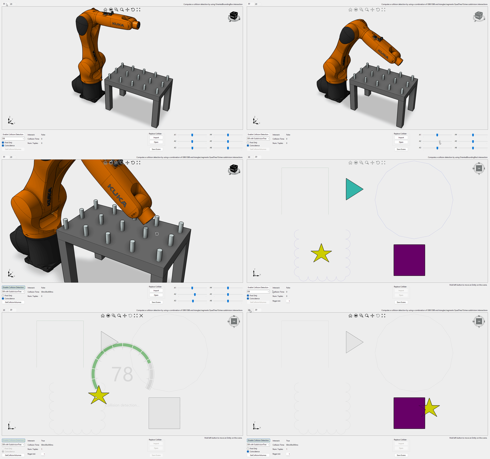
This sample explains how to properly animate a robot arm and how to check collisions between objects. The additional tab is dedicated to 2D collision detection instead. For more details on the collision detection implementation, check this this article.
CustomData
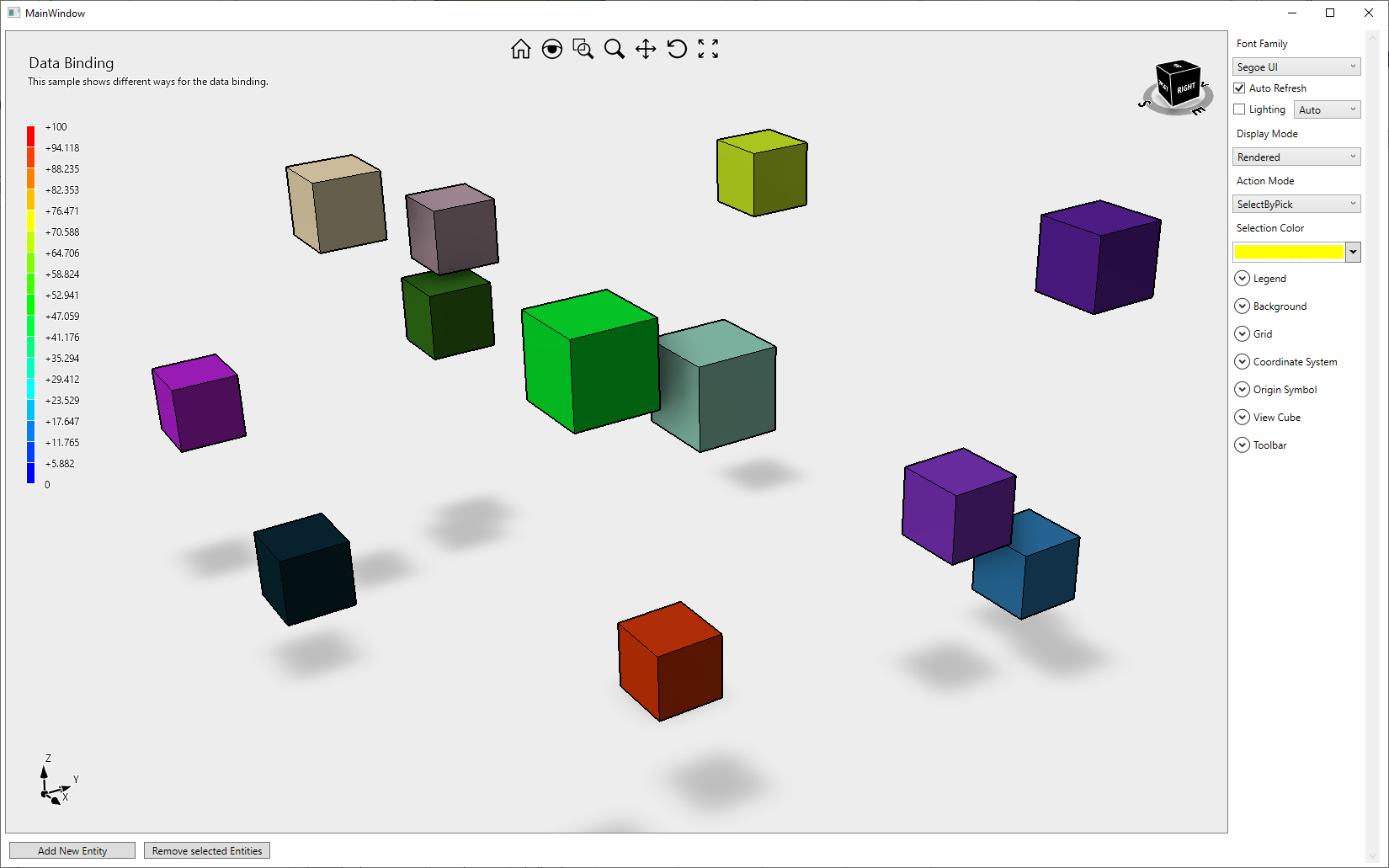
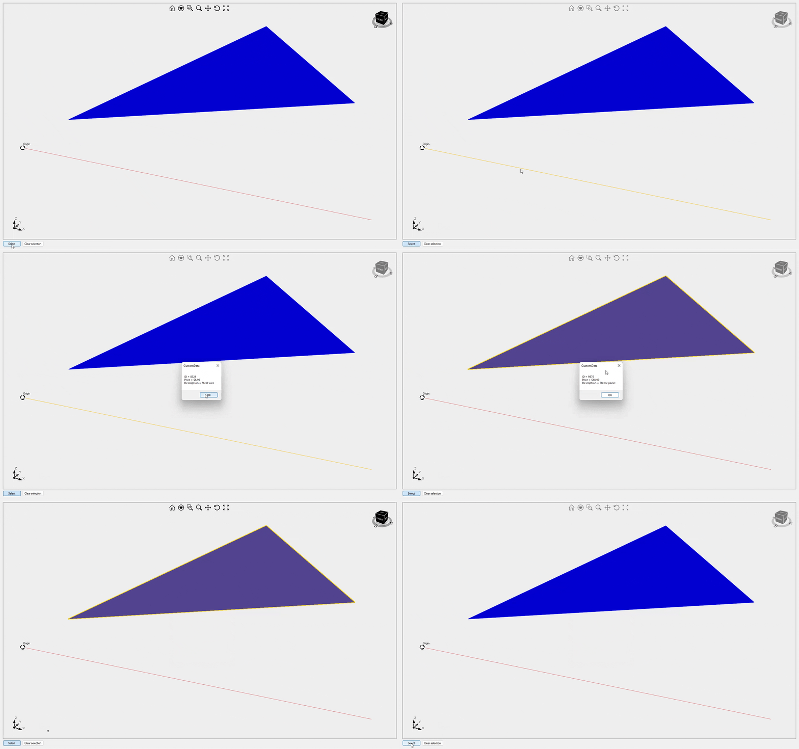
This sample explains how to add custom data to an entity and how to retrieve it at runtime. It also describes how to implement custom data cloning and serialization. If you need to extend Eyeshot entity classes instead, follow the FileFormatExtension more sophisticated approach.
CustomToolbar
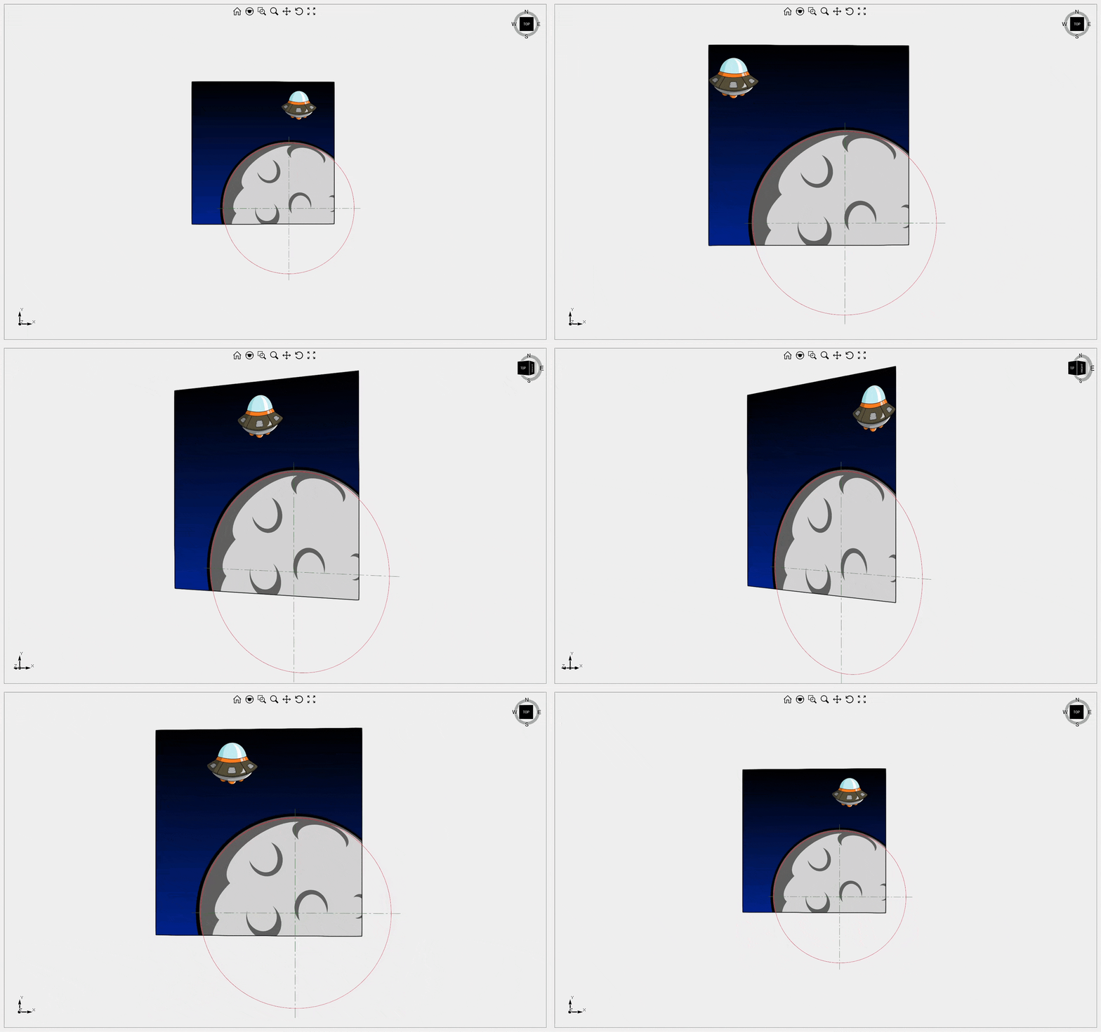
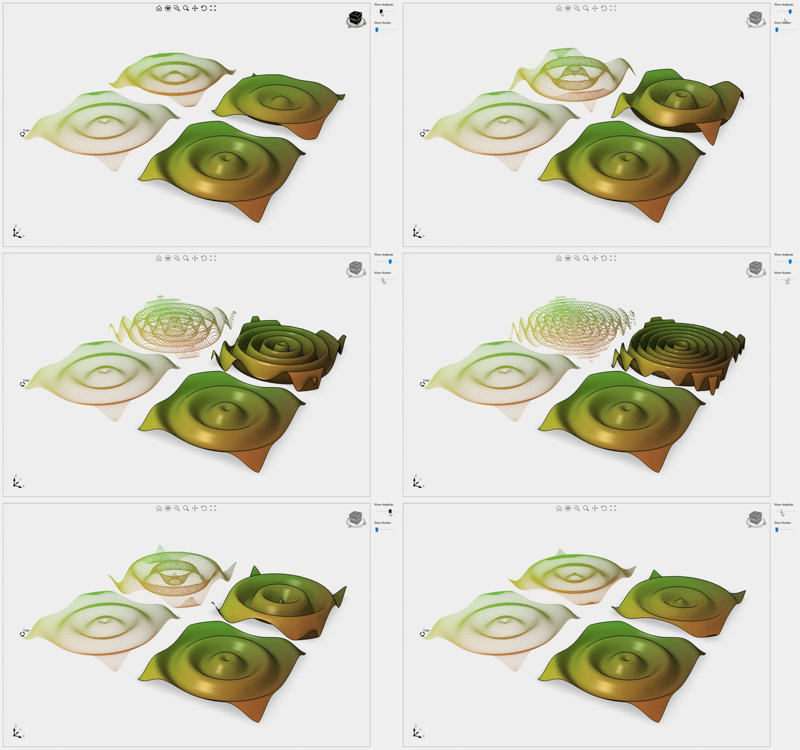
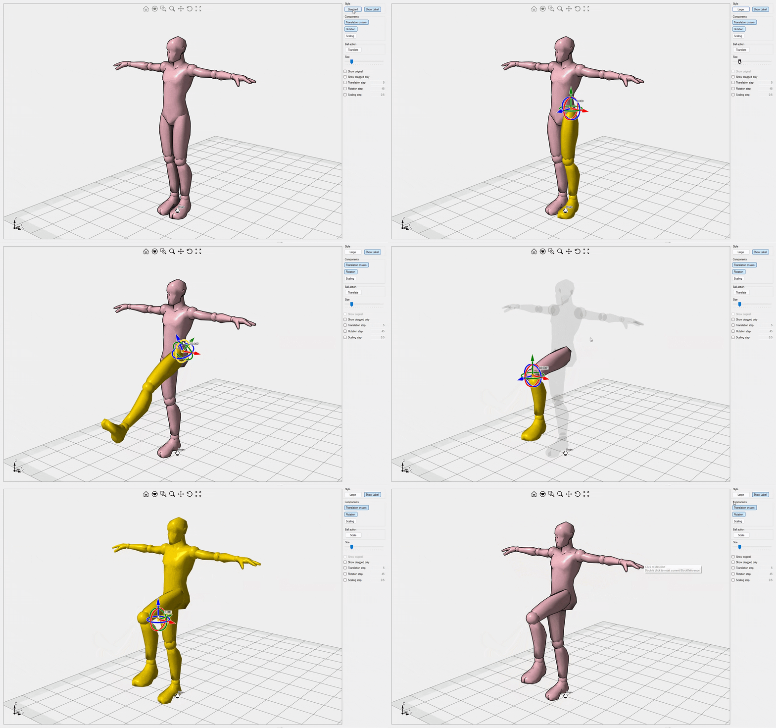
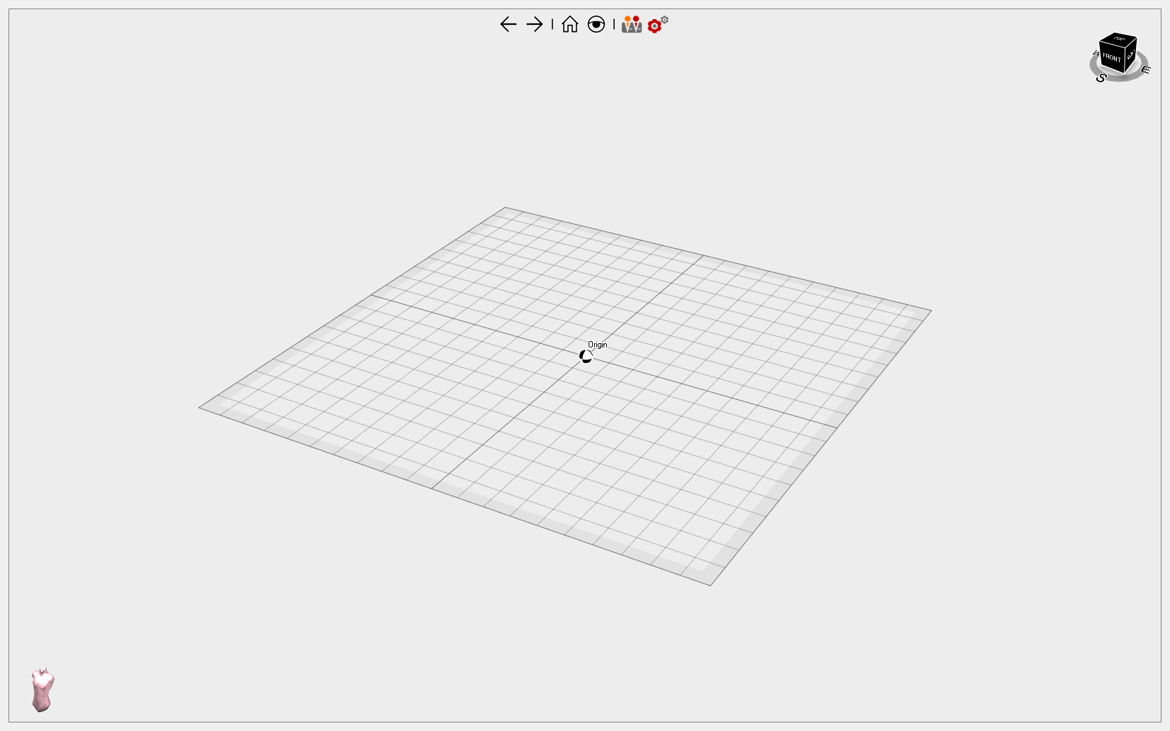
This sample provides a guide on how to add custom buttons to the Viewport toolbar and how to change the behavior of built-in buttons. It also shows how to replace the coordinate system icon with a custom list of Mesh objects. Not all applications need to display world axes; for instance, in medical applications, a torso shape might be more appropriate.
Defeature Ultimate Fem
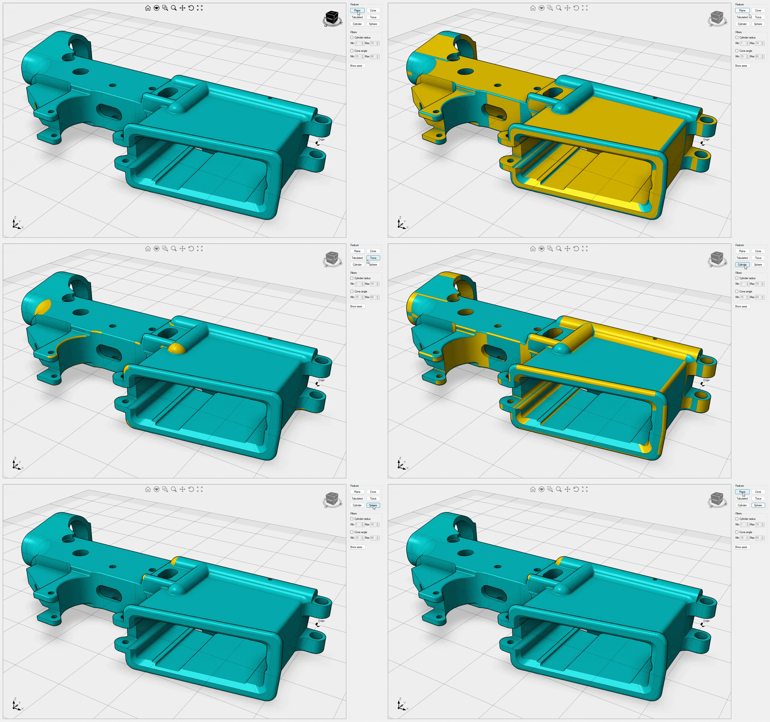
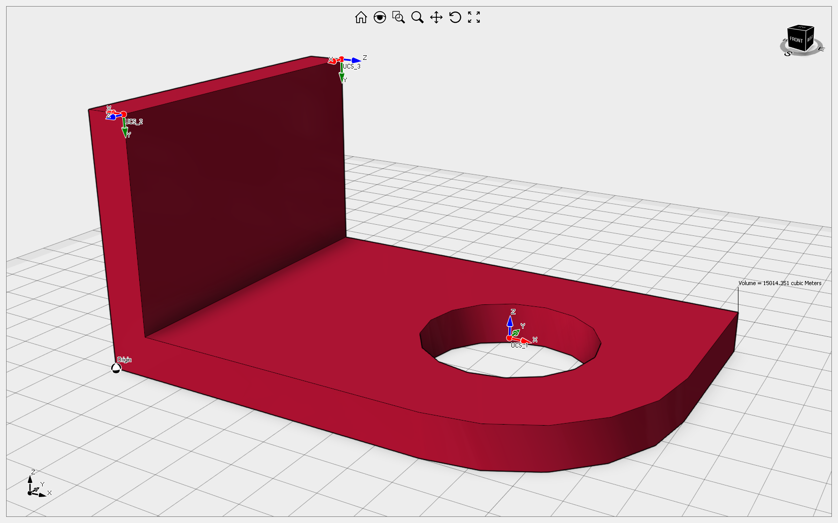
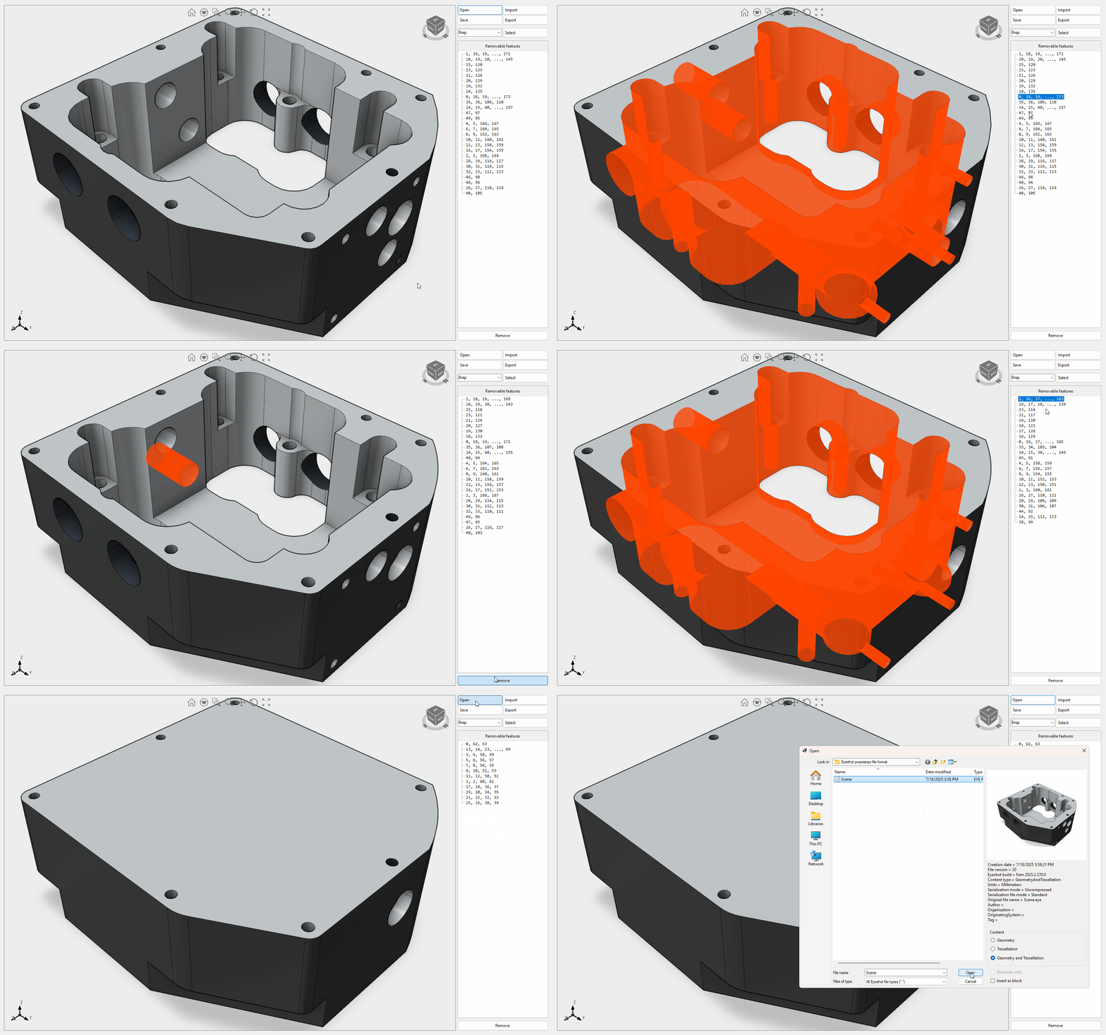
This sample demonstrates the process of identifying and eliminating topological elements from a BRep object. Video1
DelaunayTriangulation
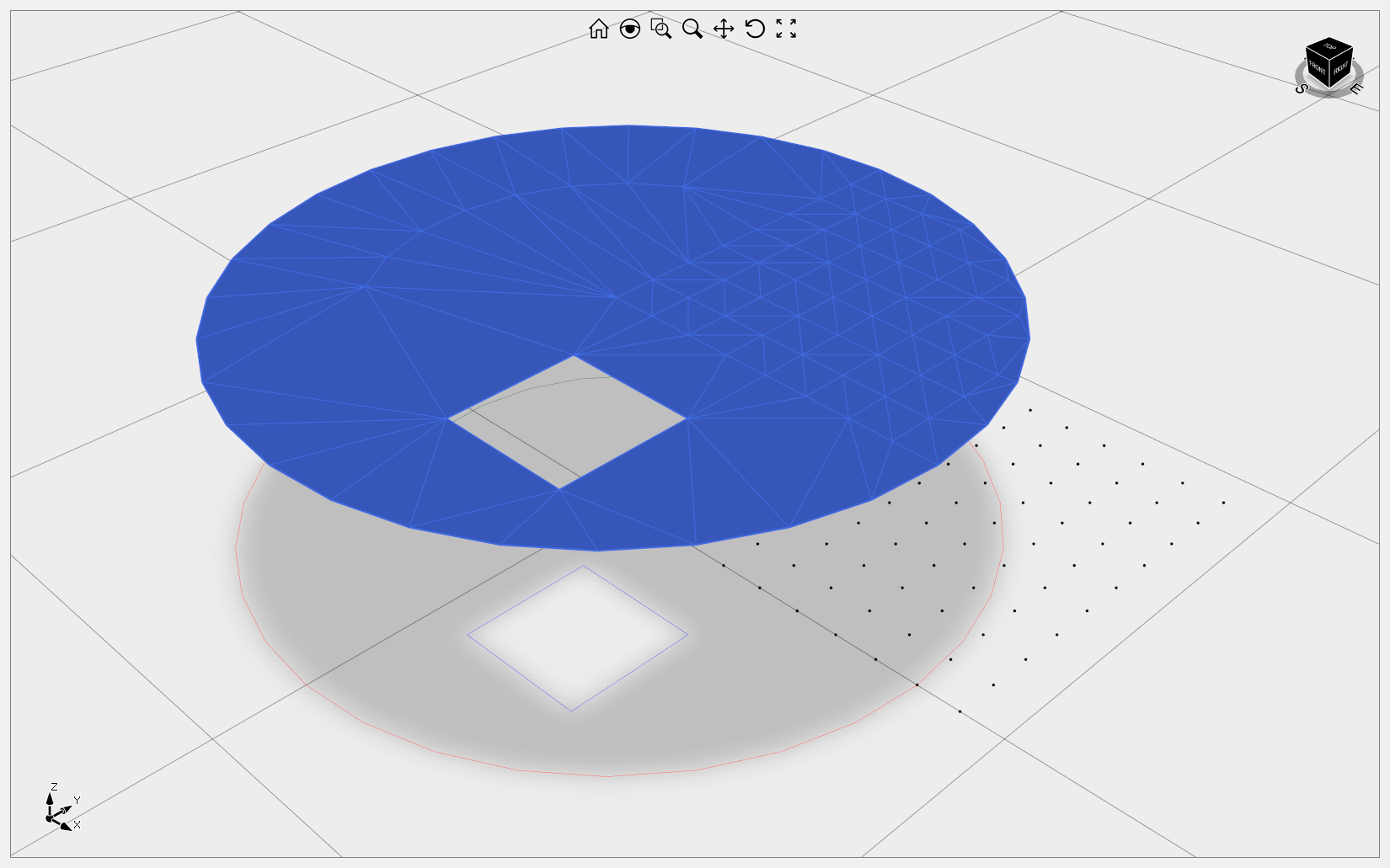
This sample demonstrates how to utilize Delaunay triangulation, which can be applied to points, loops, or both. It's important to note that the outer loop needs to be closed, meaning that the first and last points must have the same coordinates. For internal loops, they can either be closed or open. If the loops are closed, the orientation should be counterclockwise for the outer loop and clockwise for the inner ones.
DraftingDemo
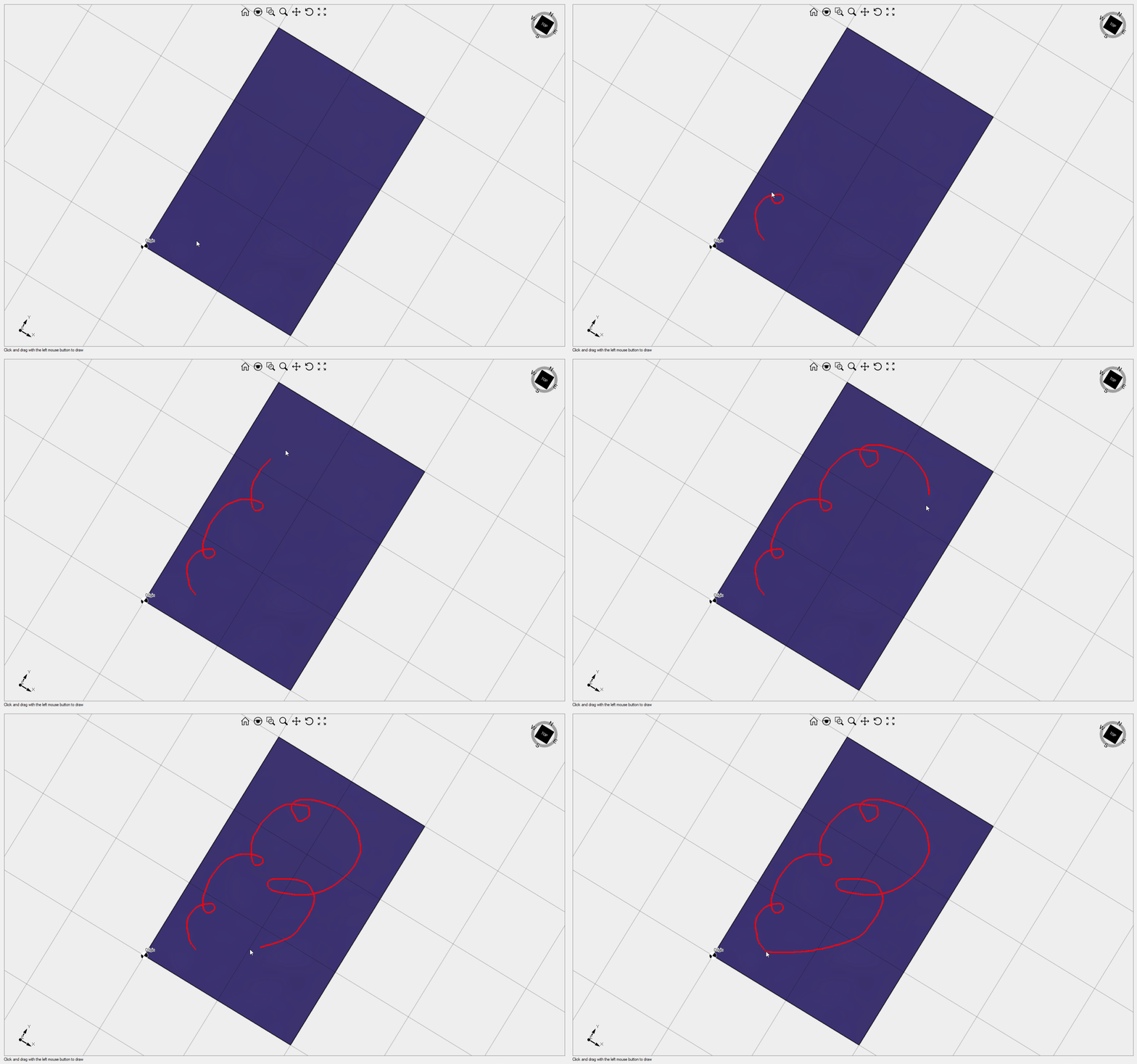
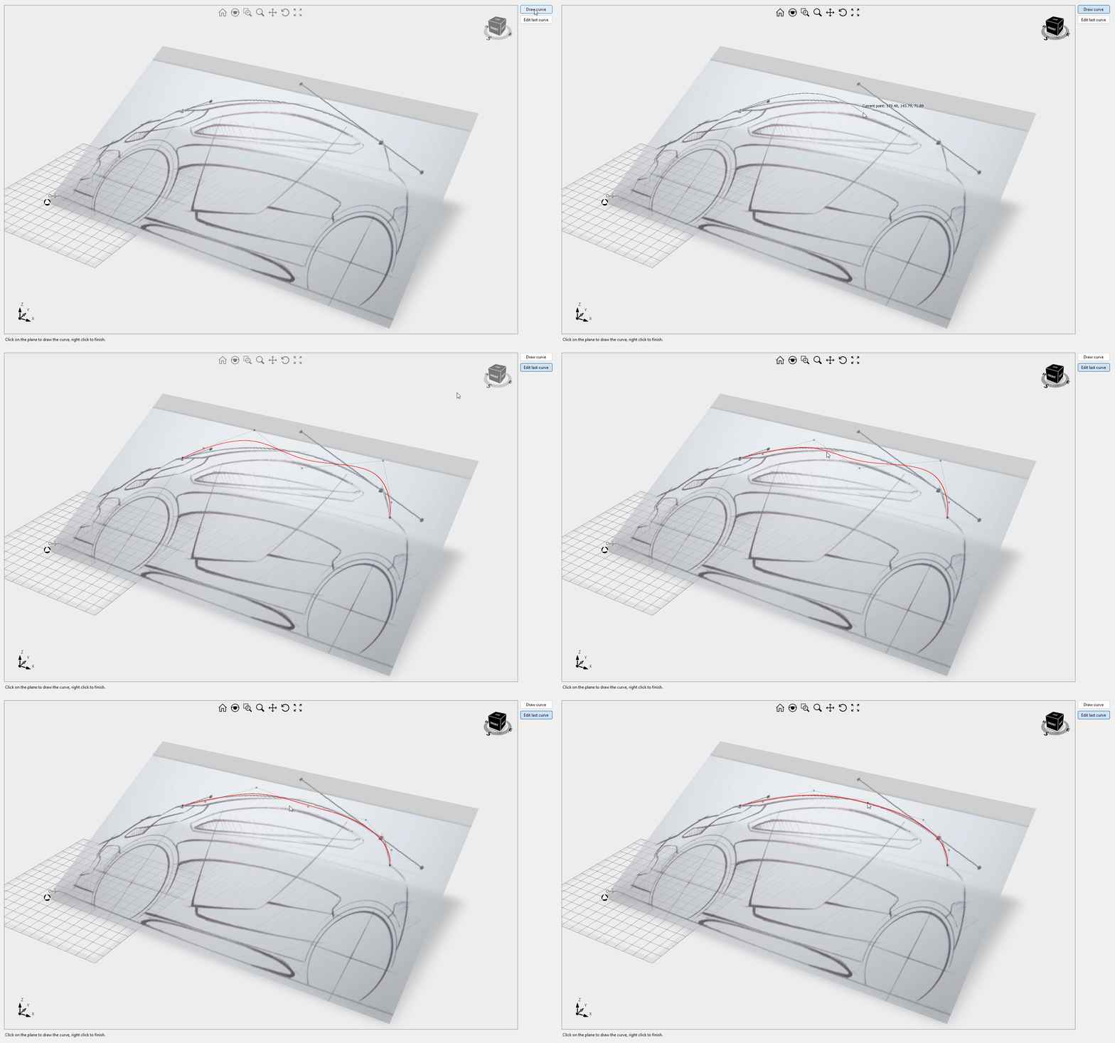
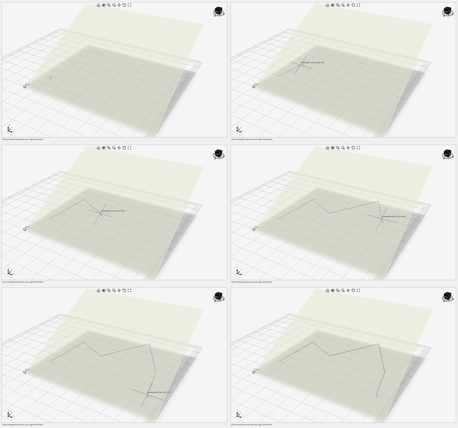
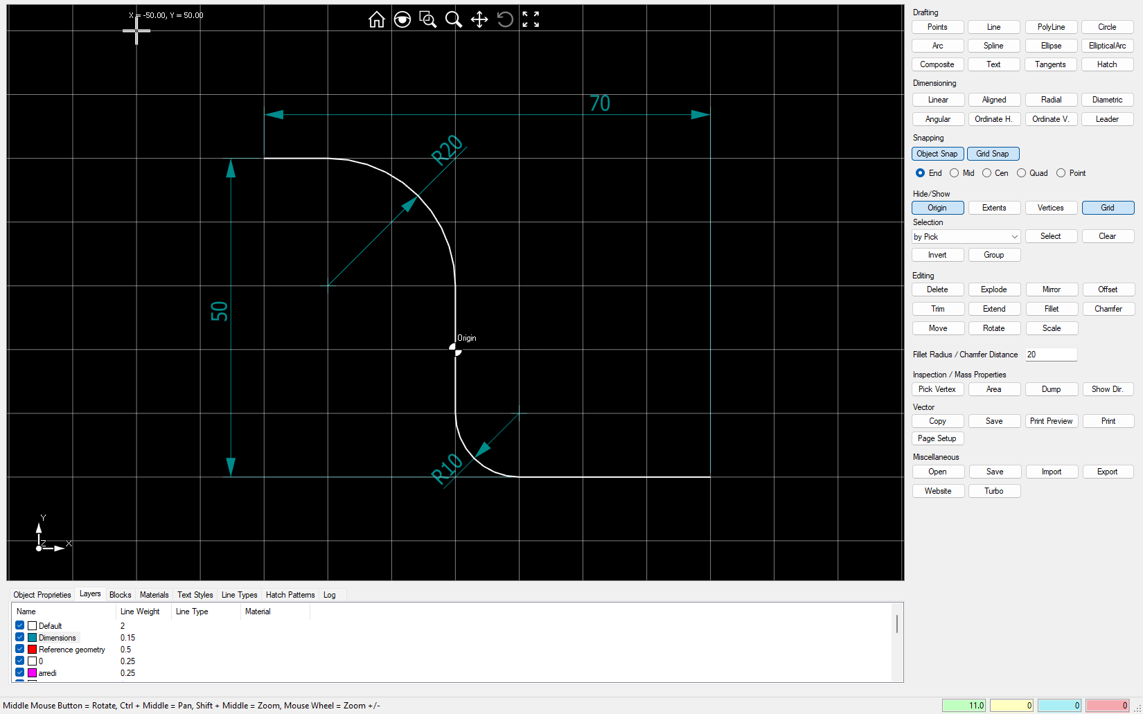
This sample demonstrates how to create interactive 2D curves and dimensions. It serves as a great foundation for building a 2D CAD system. The example also covers curve trim, extension, fillet, and chamfer. Starting from version 12, this example supports import/export from DWG/DXF and export to the 3D PDF file format. Video1
DragControlPoint Ultimate Fem
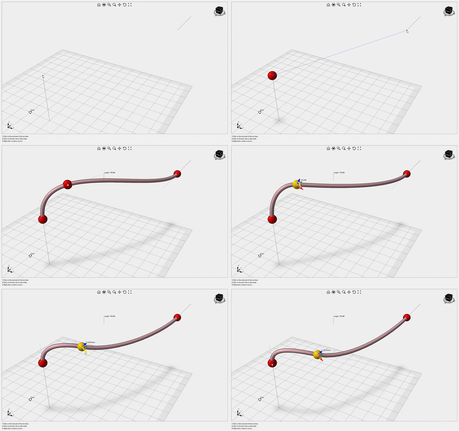
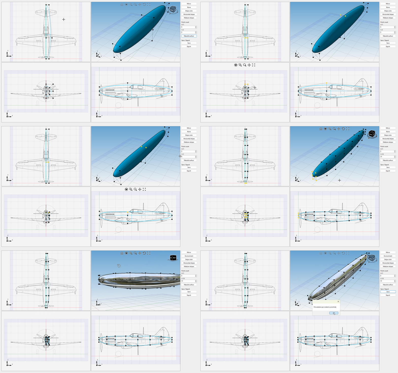
This sample illustrates how to interactively drag NURBS surface control points to model complex freeform shapes, like an airplane fuselage. Video1
EyeshotDemo
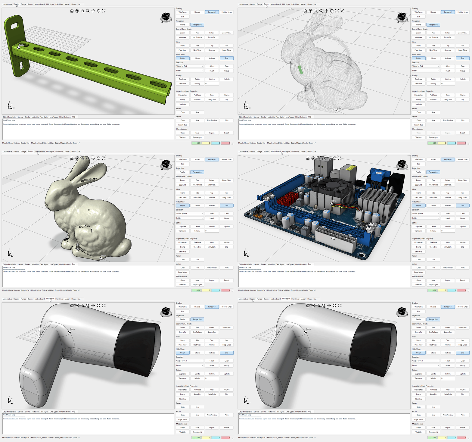
A fully-featured application that demonstrates the capabilities of the Design control. Video1
FileFormatExtension
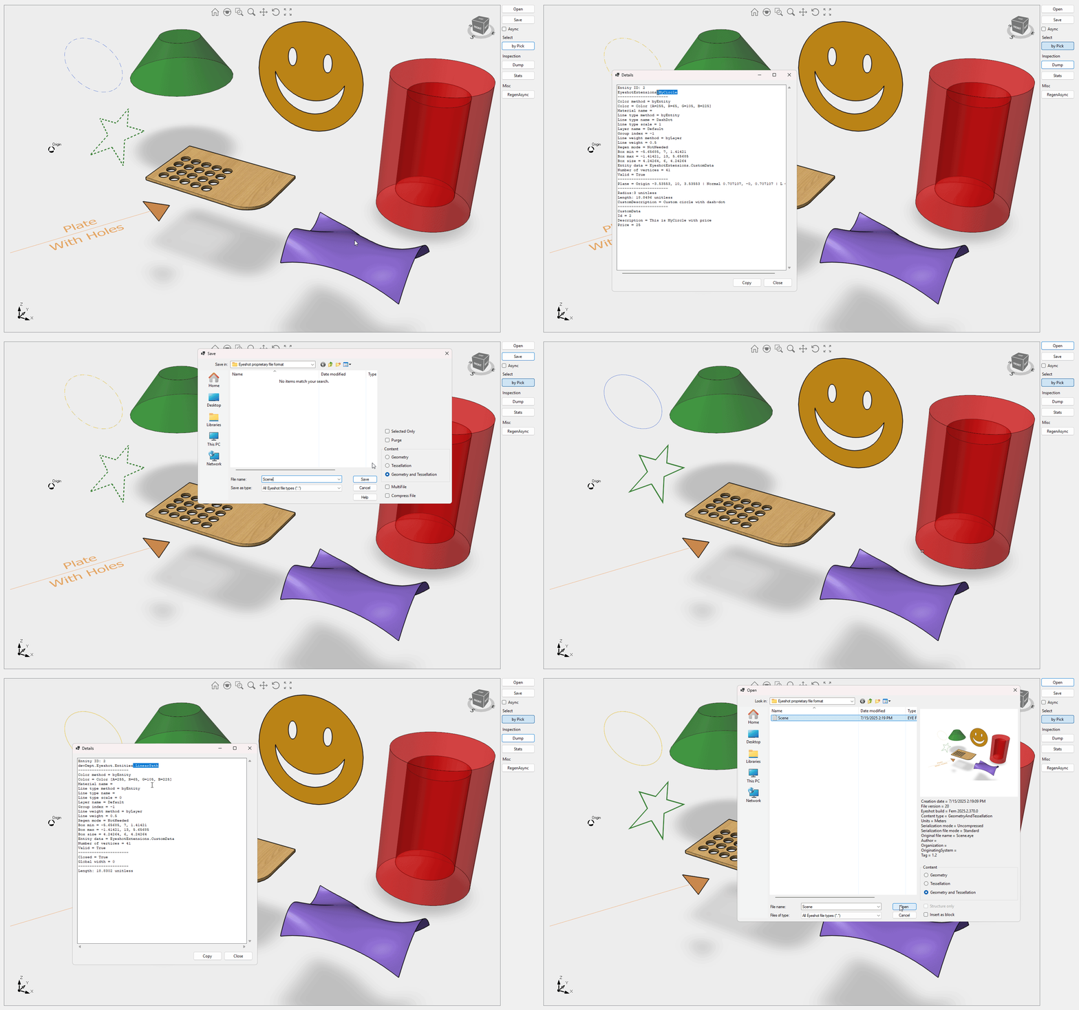
This sample explains how to extend Eyeshot's proprietary file format with custom data and custom entities. For additional information, please refer to this article. When dealing with custom data, it may be beneficial to explore an alternative approach, such as the one demonstrated in this code sample, which does not involve versioning.
FirstPerson
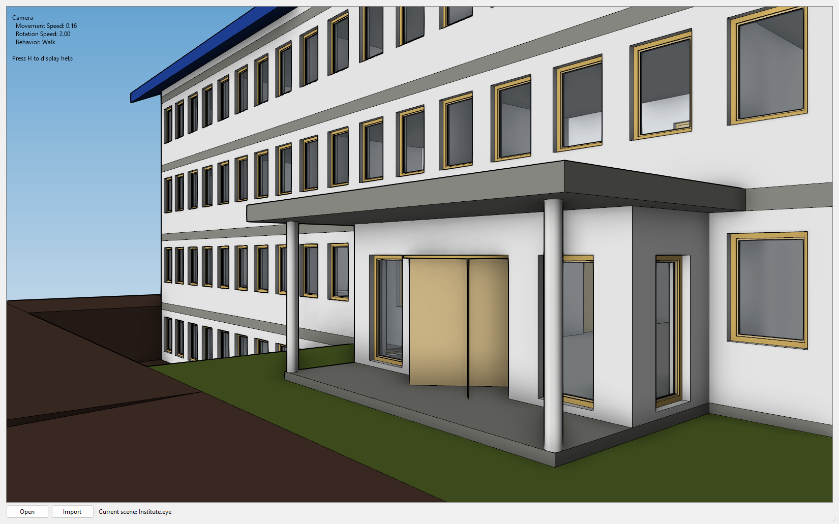
This sample demonstrates how to alter the viewport navigation method using the Viewport.Navigation.Mode property. Use the WASD keys to navigate. Video1
GroupSimilar
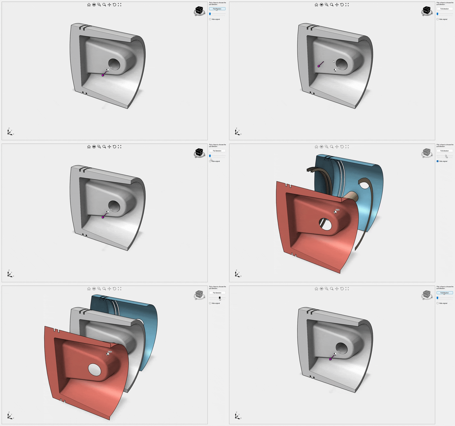
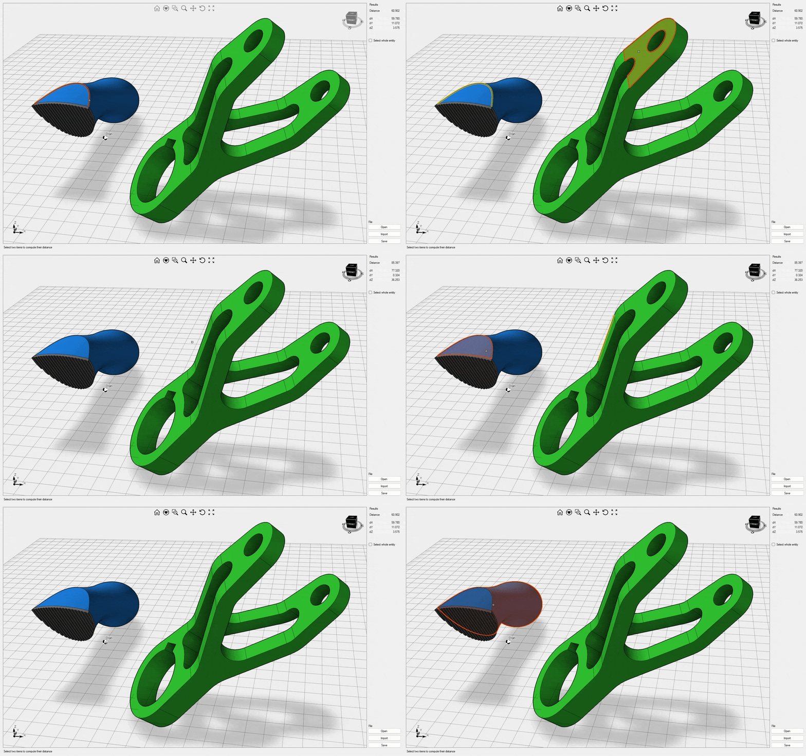
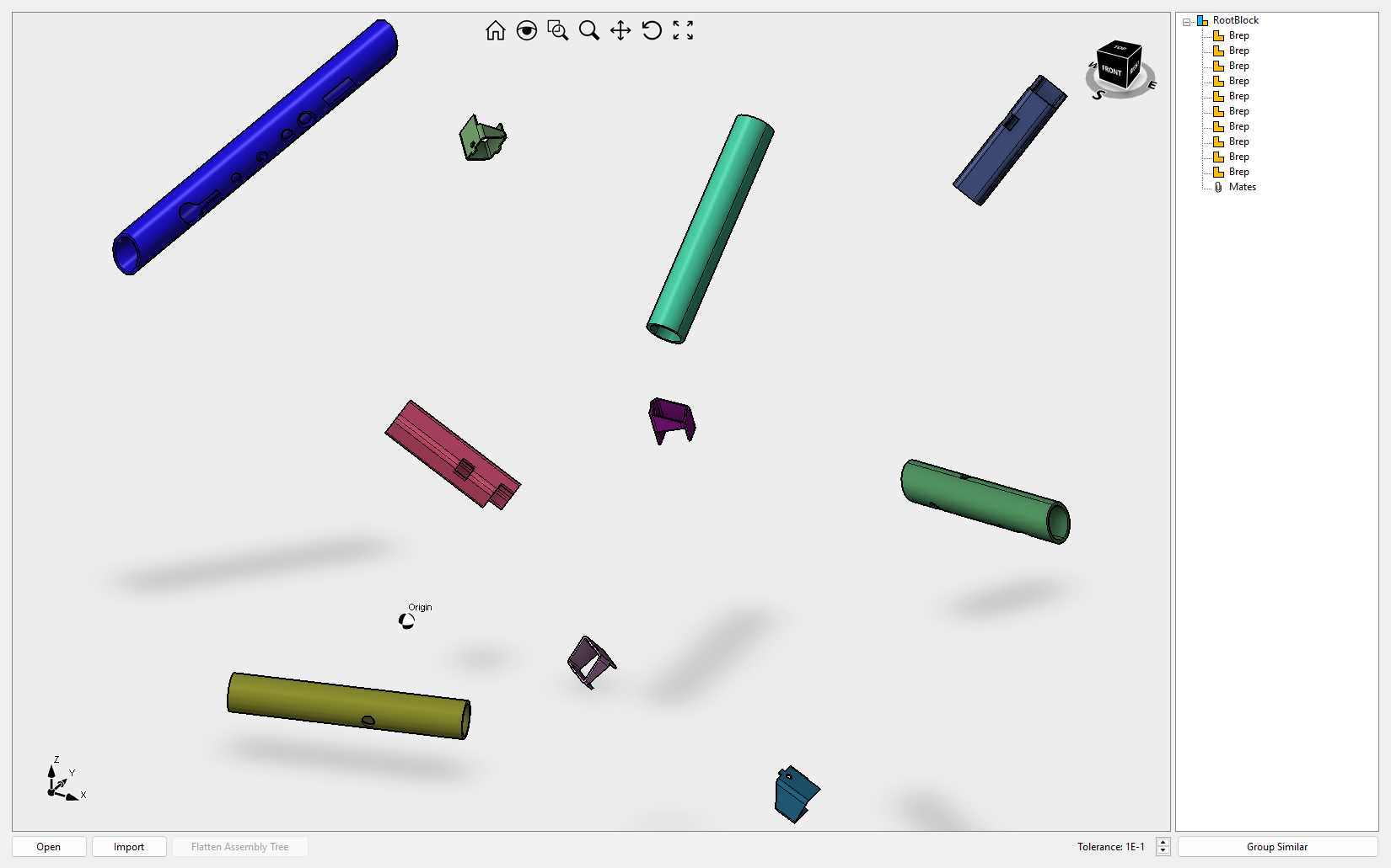
This sample explains how to use the FindSimilar class. Based on the invariant properties under roto-translation of 3D objects, this class can identify all 3D objects with the same shape and rebuild an assembly tree containing unique objects (mirrored included). Video1
ImGui Ultimate Fem
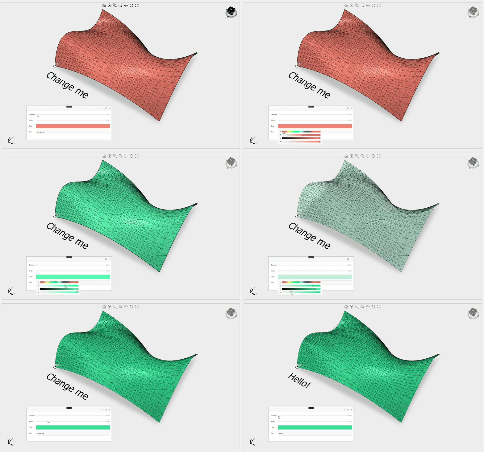
This sample demonstrate how to use the QuickForm tool described here to interactively change the NURBS surface tessellation.
MachineSimulator
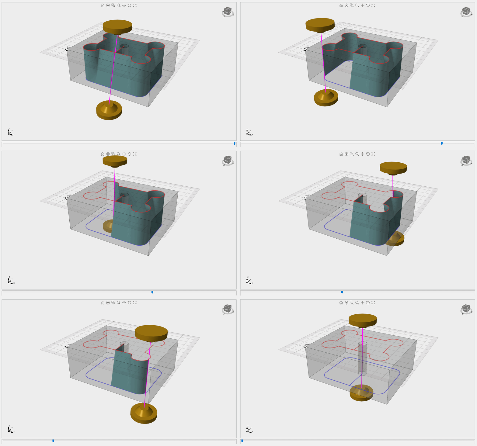
This sample demonstrates how to simulate the movements of a 3-axis CNC machine. Initially, the moving components are loaded from STL files and incorporated into three distinct block definitions. Subsequently, three subclassed block references override the Animate() and MoveTo() methods to calculate the new position and move the objects (on GPU only). Additionally, it illustrates how to overlay drawings over all UI elements.
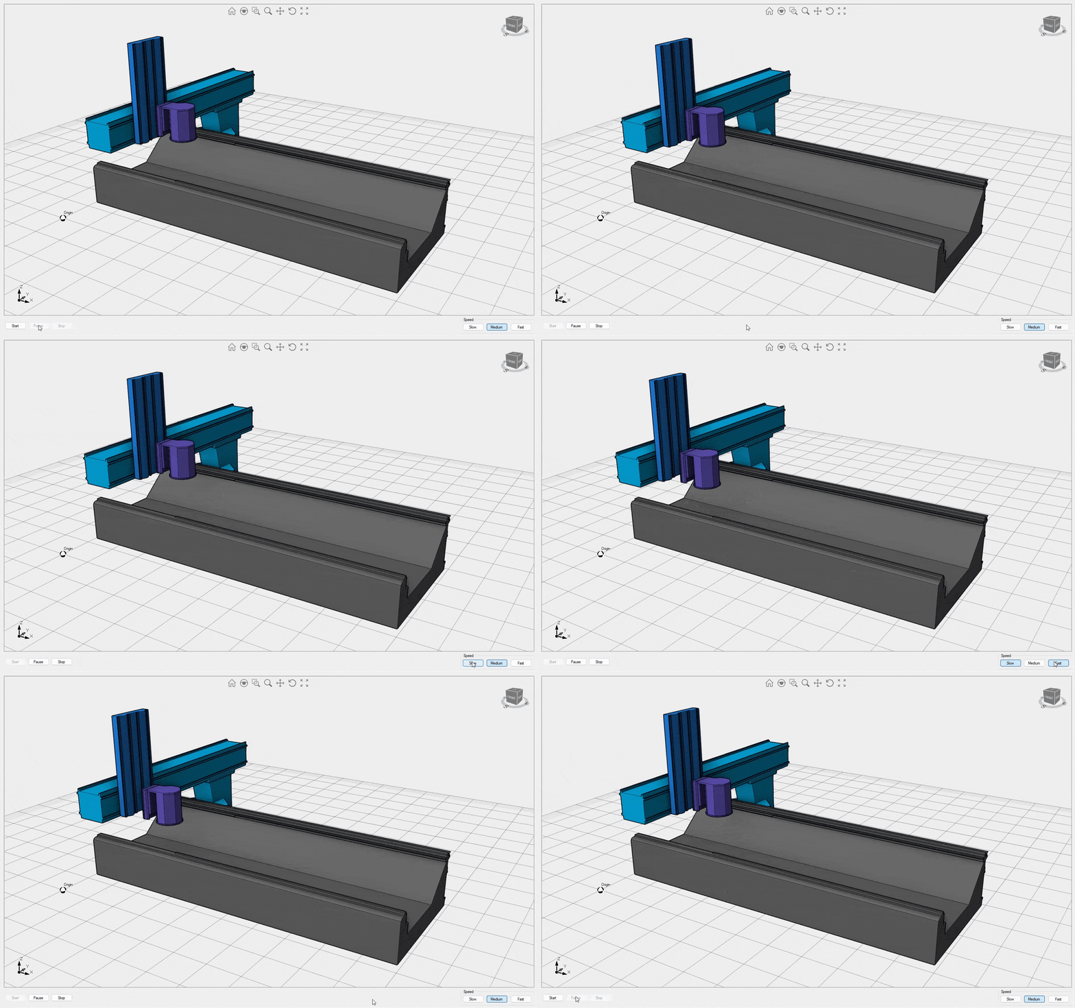
MeshEditor
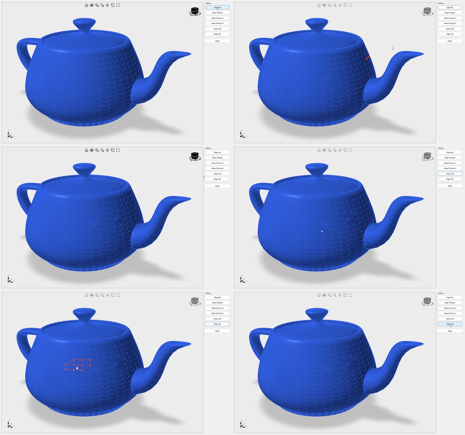
This sample illustrates how to modify mesh triangles and vertices using the MeshEditor class. The available operations include edge flipping, edge collapsing, vertex dissolving for vertices connected to 3 or 4 triangles, vertex cell, and edge cell. Video1
PaperDemo
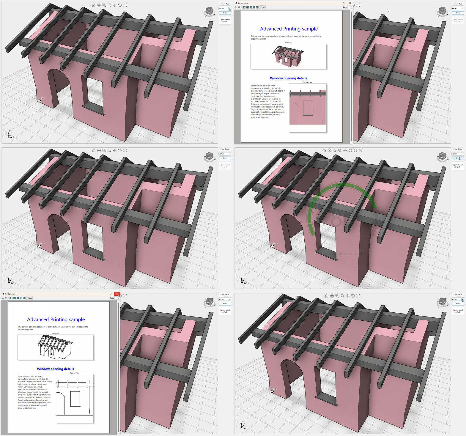
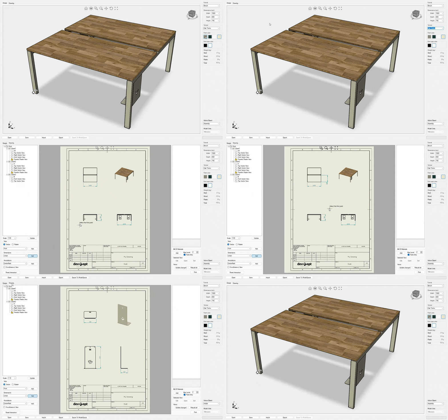
This detailed demonstration explains how to generate Vector and Raster views of your geometry in the Drawing workspace. It is the only example that allows for the import of DXG/DXF files that include AutoCAD paperspace or layouts. Import of STL, OBJ, IGES and STEP files are provided to test the view generation quality on your own geometry. The Drawings tab contains a variety of options to add dimensions and annotations to the views. Drawing sheets can be exported to DWG/DXF as VPORT objects or exploded curves. Yes, you are right, the geometry belongs to our office desks as you can check here. Additionally, this demonstration shows how to use the WorkManager class to handle a queue of WorkUnits for building the views. Ready to start? Check this introductory article for more information. Video1, Video2
PerformanceStudio
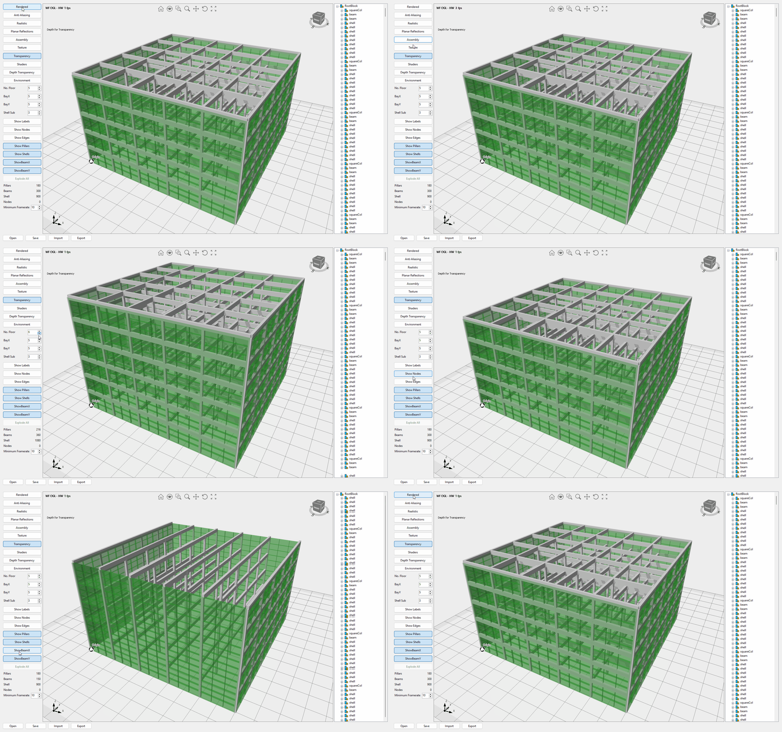
This sample shows how each graphical setting impacts drawing speed. It also showcases the scene graph being rebuilt as a single object, multiple objects, and hierarchical objects. One notable aspect of this example is the depth of transparent objects. When enabled, it allows for accurate values to be obtained under the mouse cursor, even for transparent objects. This affects 3D coordinate extraction and the determination of the center of rotation.
SceneEditor
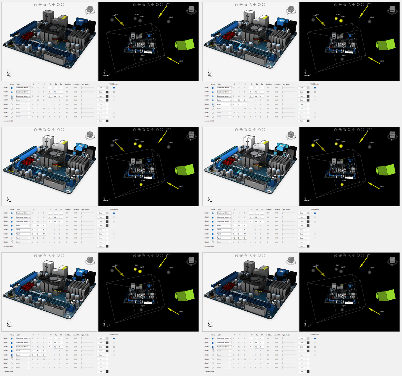
This sample gives you full control over the scene lighting settings. On the left pane, you can see the camera view, while on the right pane, you can see the 3D scene from the director's point of view. You can turn on up to eight lights of point, spot, directional, and stationary types, and change the settings for each light. Currently, only one light can cast shadows. You'll also find the code to copy geometry from one Design control to the other.
SelectTriangles
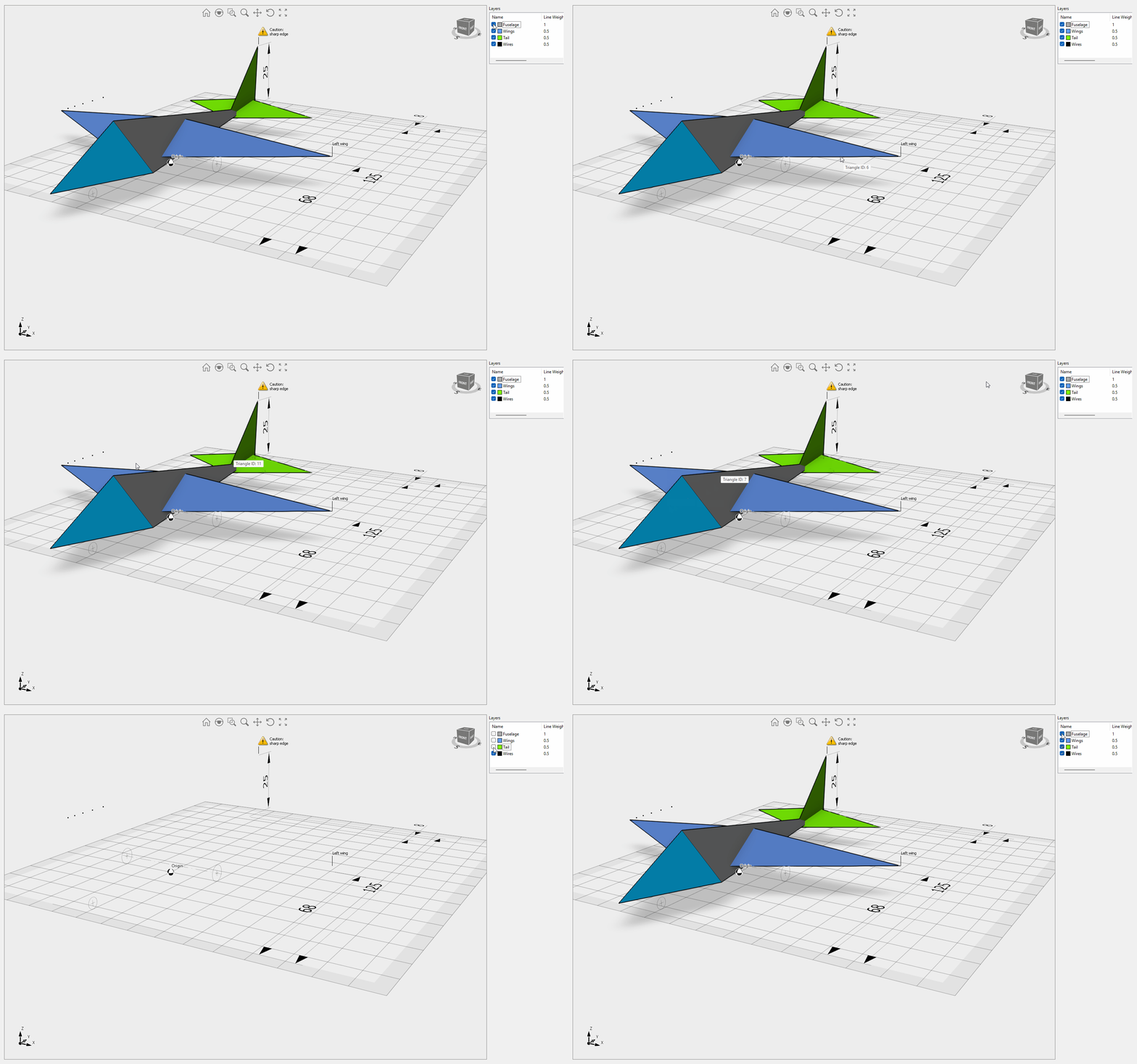
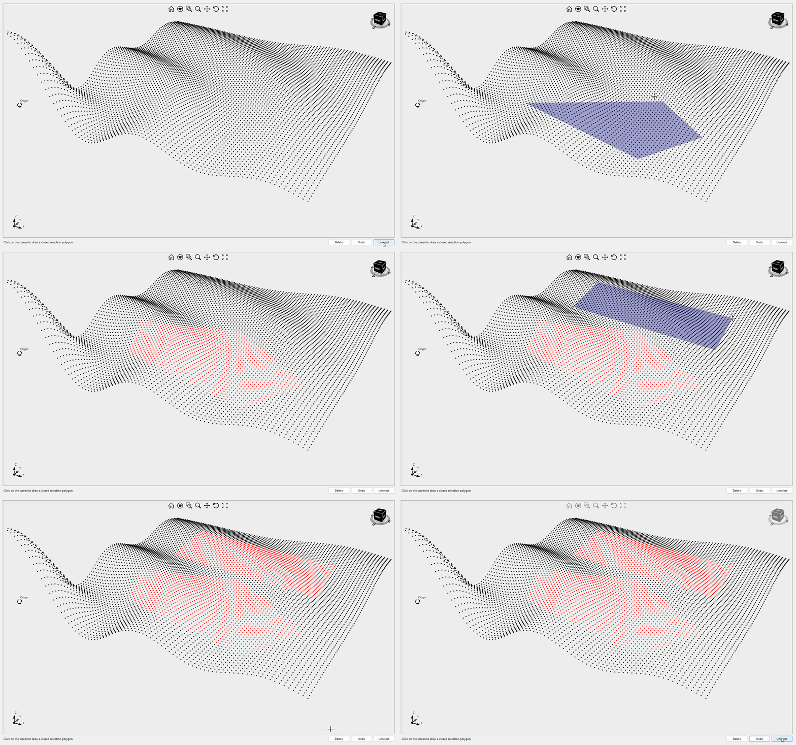
This sample explains how to implement individual mesh triangle selection or individual linear path segment selection (Lines tab). The sample is optimized for large objects (high number of vertices) and implemented using vertex buffers.

Simulation Fem
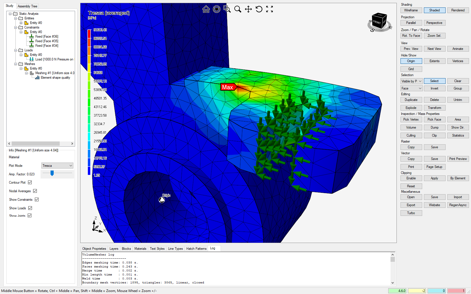
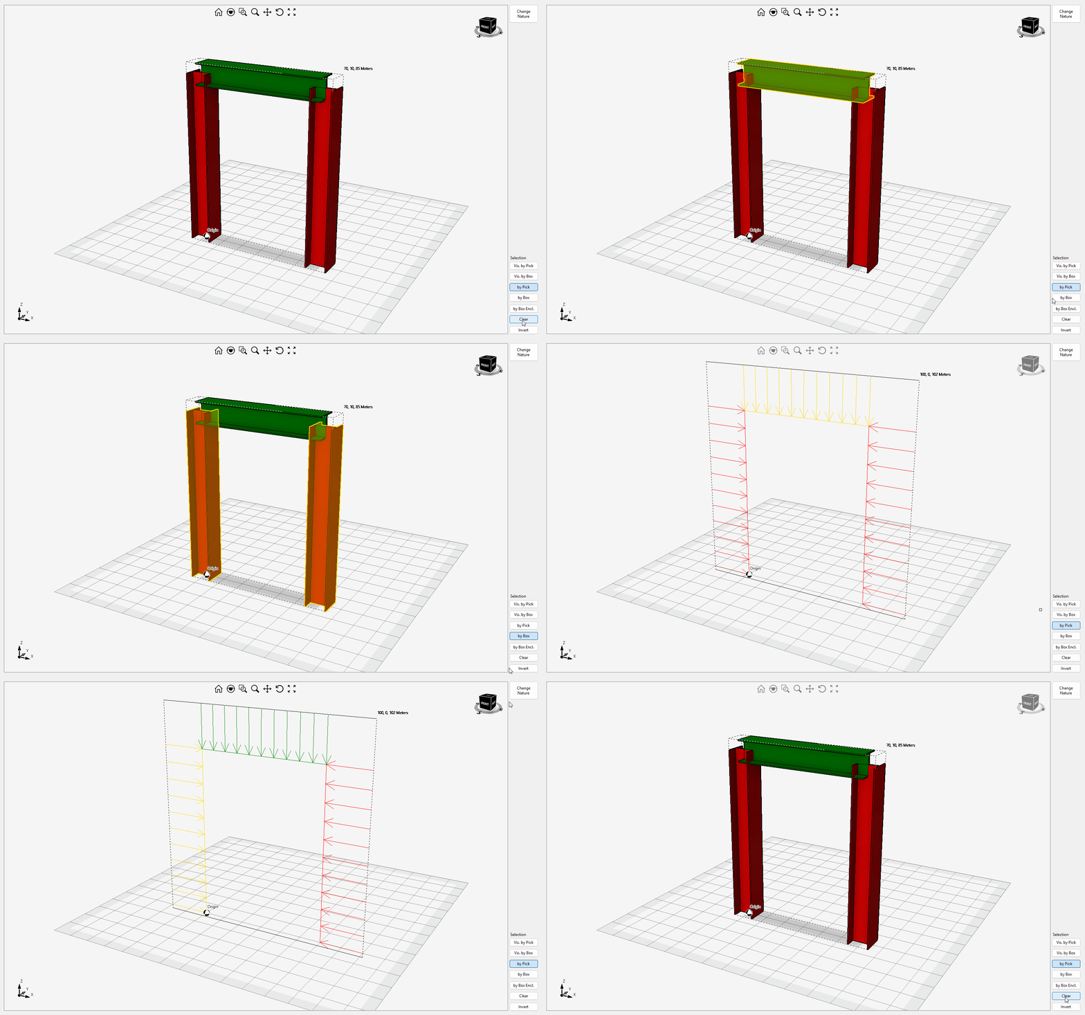
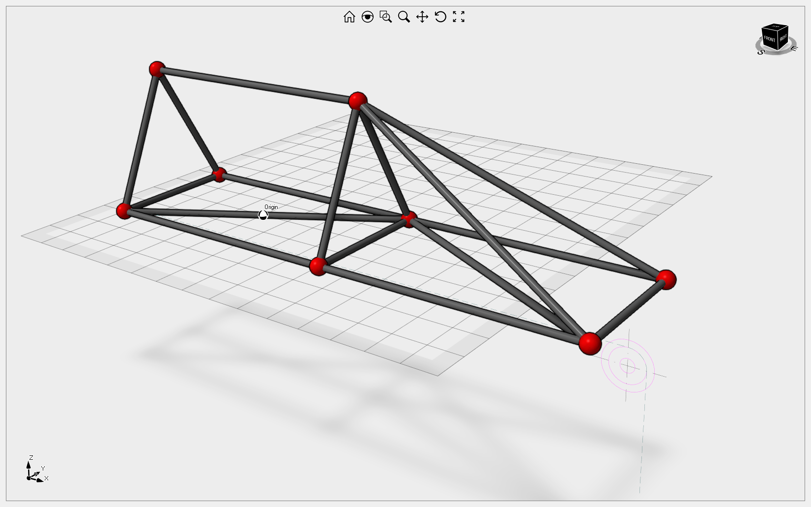
This sample illustrates Eyeshot's Finite Element Analysis capabilities, including mapped meshing and 2D and 3D beams with hinge support. Clicking the "Numeric results" button opens a dialog displaying all the results in a tabular view. Video1
SketcherDemo
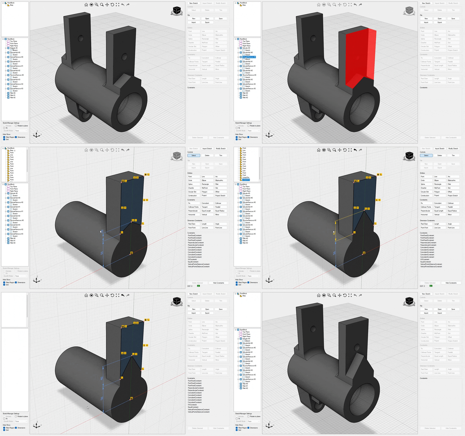
This sample shows how to utilize the 2D constraint solver from UI, including sketch extrude/revolve/sweep and assembly navigation to a specific component/BRep. The left pane contains the assembly and features trees, and it also offers the option to import a sketch from DWG/DXF. Video1, Video2, Video3
SlicerDemo
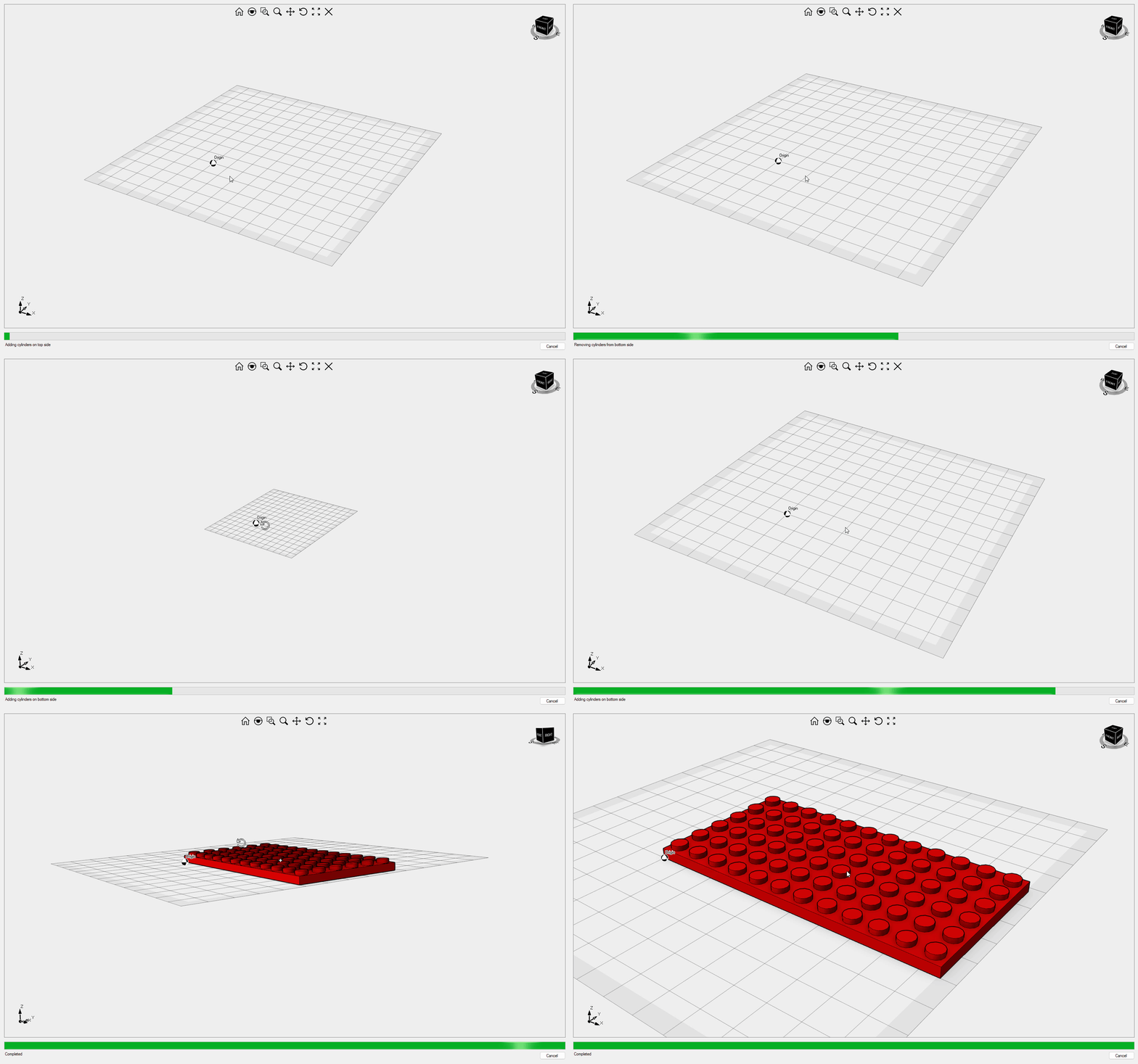
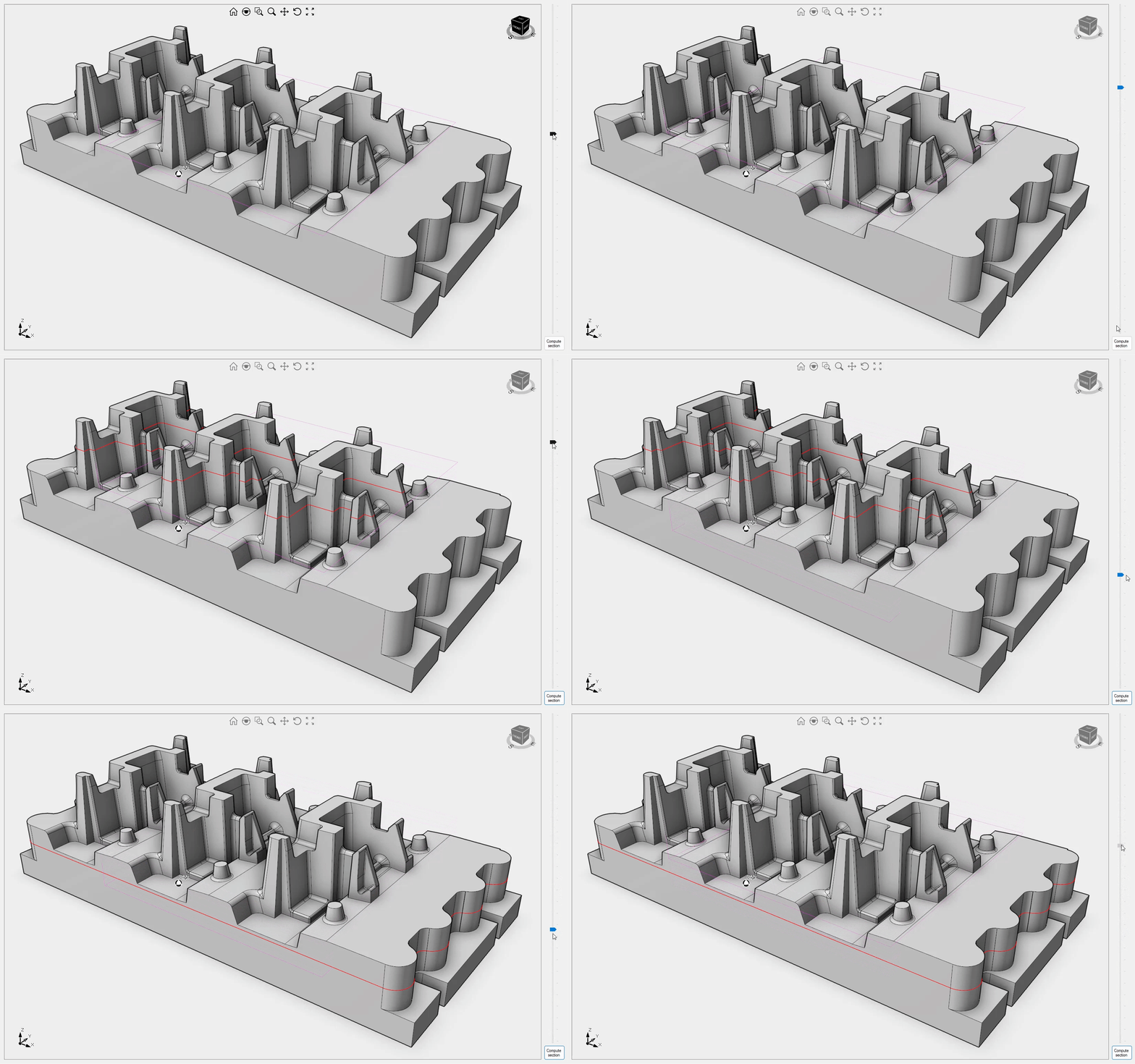
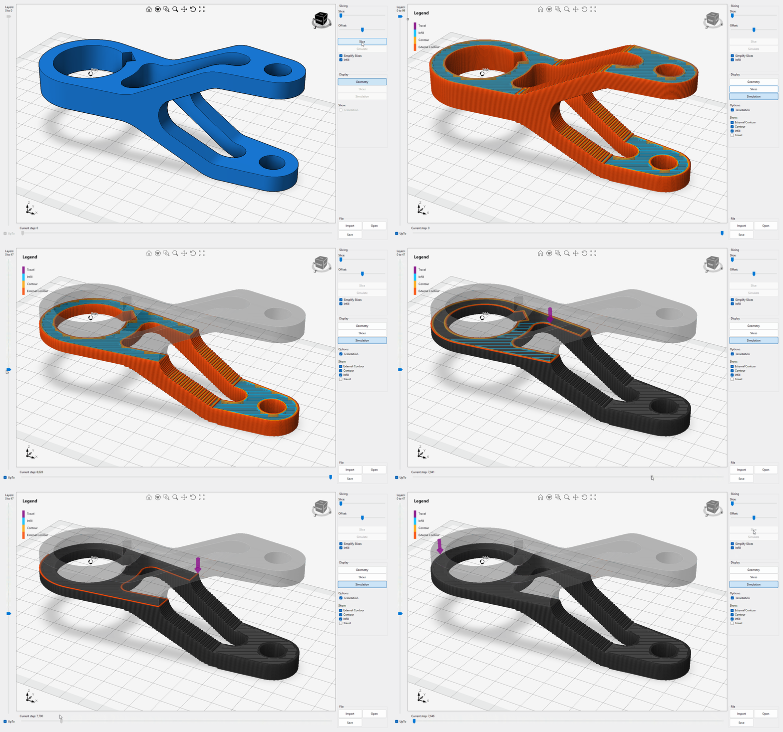
This sample provides instructions for slicing a 3D mesh for printing and simulating the extrusion process. Video1
SurfaceMesher Fem
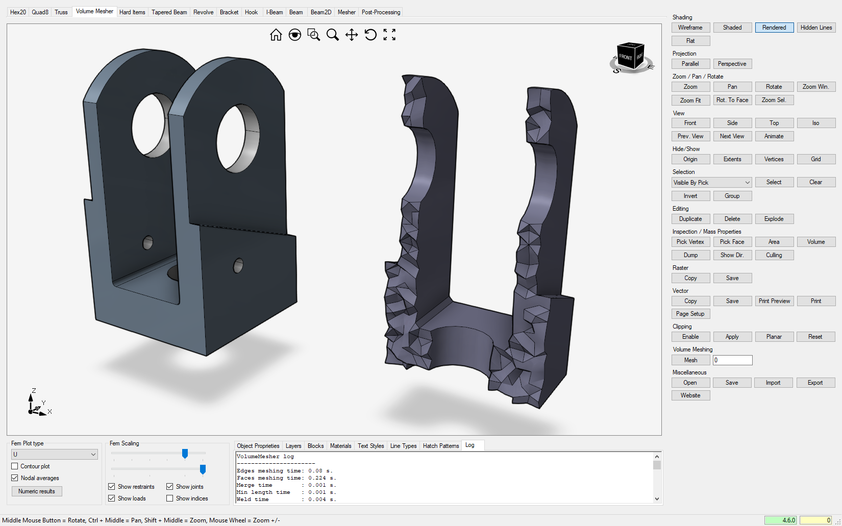
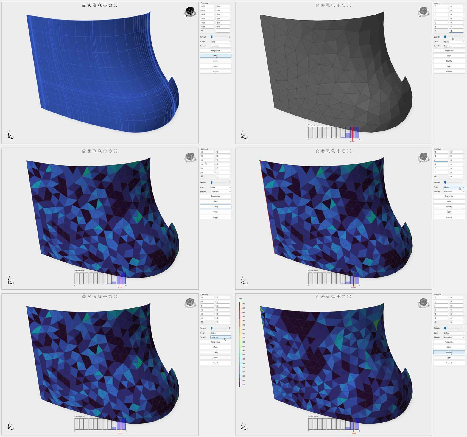
This sample explains how to control the size of elements in surface meshing and provides tools for evaluating the quality of triangle shapes. Video1
TextureMapping
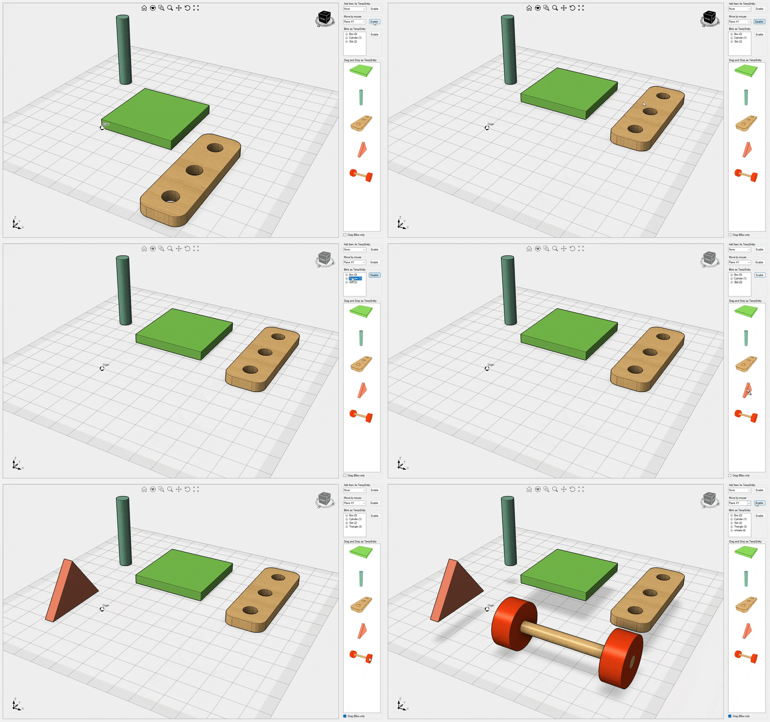
This sample explains how to apply different texture mappings to scene objects. You can experiment with each mapping and scaling combination by simply dragging the desired material onto the scene object. Additionally, it demonstrates how to create realistic materials. Video1

Workspaces Ultimate Fem
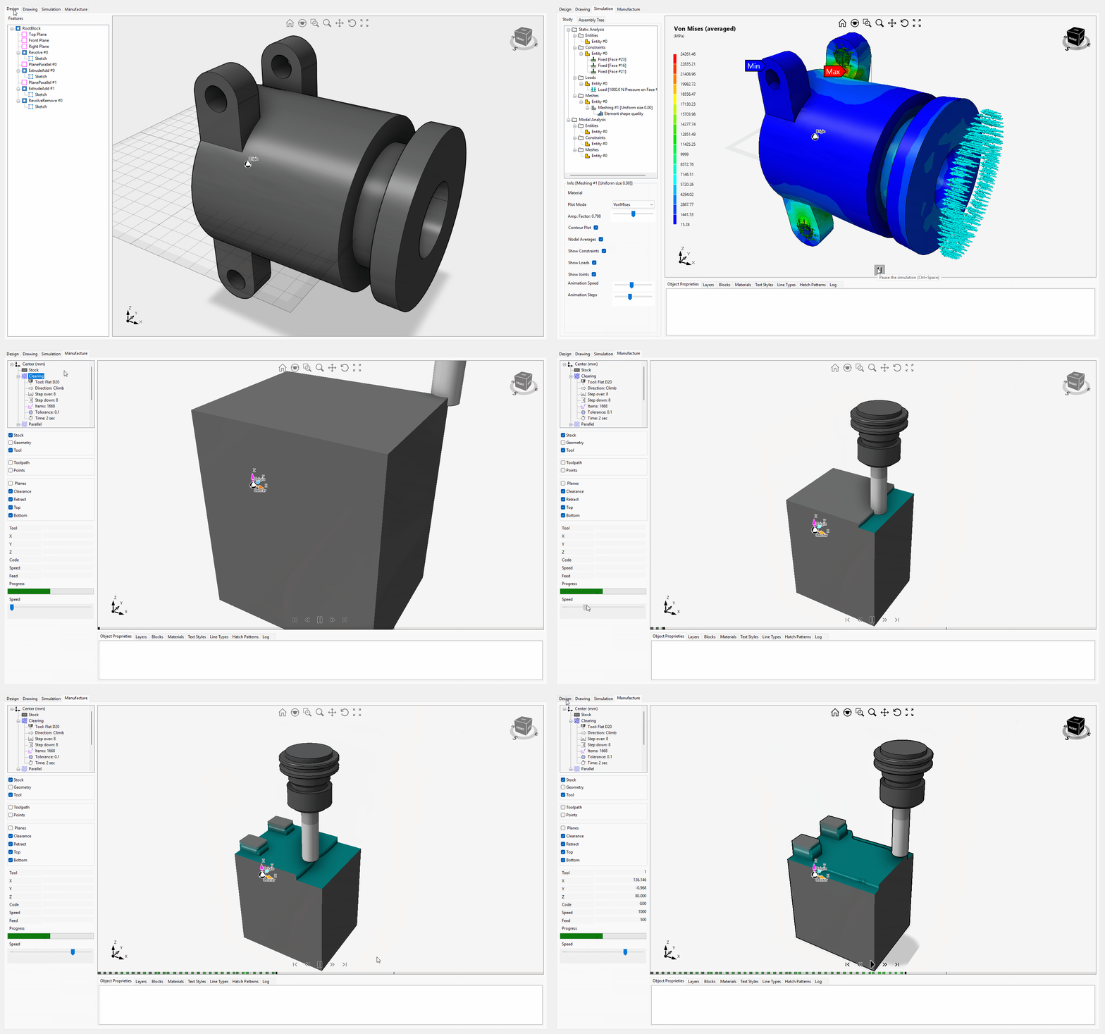
This sample showcases how Eyeshot workspaces (previously known as Environments) seamlessly operate on the same geometry. It also demonstrates the process of defining 2D sketches, orthographic views, FEA study, and 3x CNC machining programmatically. Video1
EditMesh
This sample explains how to utilize the MeshEditor class for simplifying an imported STL mesh. Video1
MeshCurve Fem
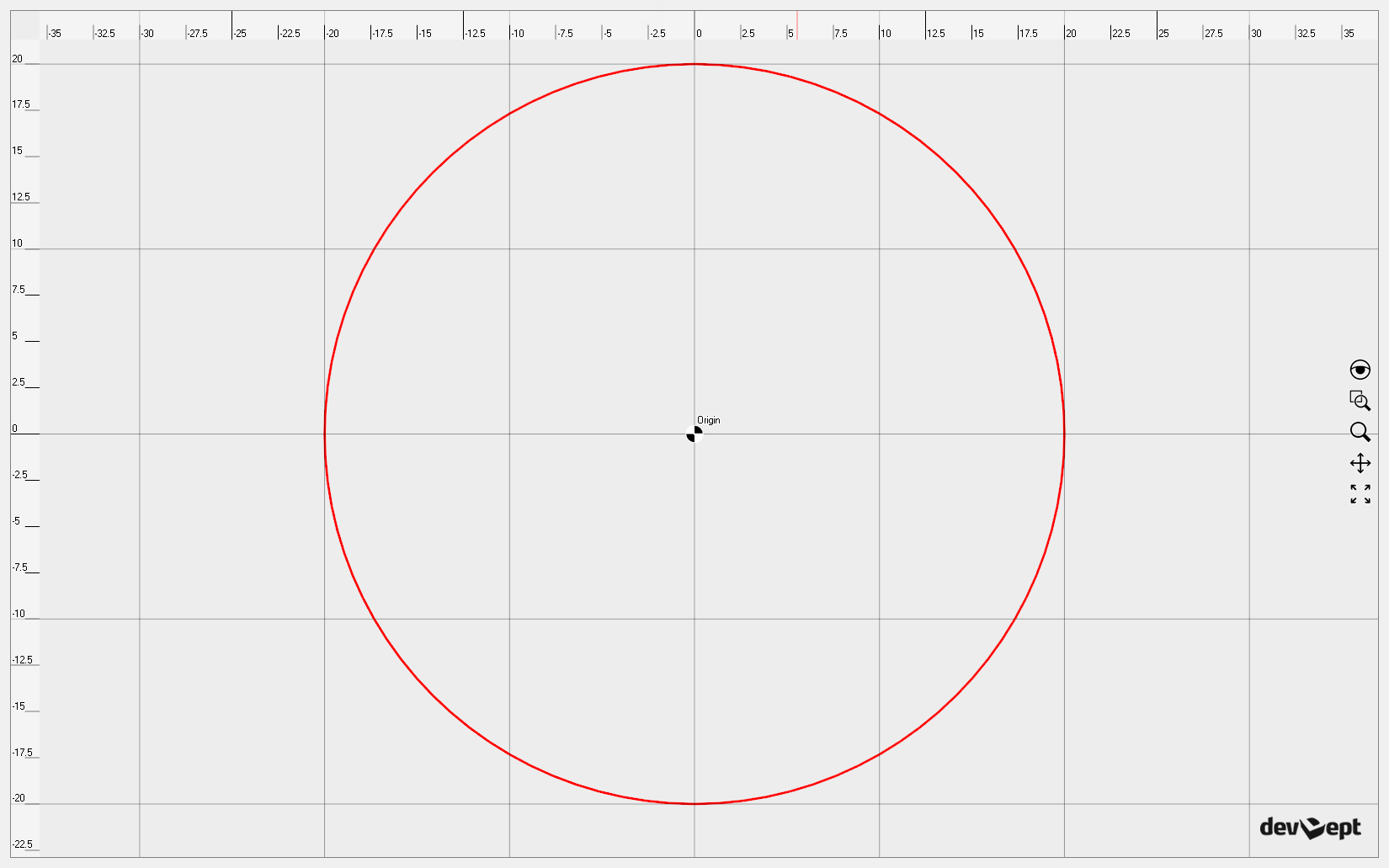
This sample demonstrates how to subdivide a NURBS curve using a variable step. Video1
